

Schema mea este

Alte poze de la montajul realizat de Bogdan:


// http://nicuflorica.blogspot.ro/2014/04/indicator-date-mediu-pentru-masina-3.html
// original sketch by niq_ro
#include <LiquidCrystal.h>
// folosesc libraria pentru afisaje LCD simple
LiquidCrystal lcd(7, 8, 9, 10, 11, 12);
// indic modul de legare, vezi mai jos:
/*                                    -------------------
                                      |  LCD  | Arduino |
                                      -------------------
 LCD RS pin to digital pin 7          |  RS   |   D7    |
 LCD Enable pin to digital pin 8      |  E    |   D8    |
 LCD D4 pin to digital pin 9          |  D4   |   D9    |
 LCD D5 pin to digital pin 10         |  D5   |   D10   |
 LCD D6 pin to digital pin 11         |  D6   |   D11   |
 LCD D7 pin to digital pin 12         |  D7   |   D12   |
 LCD R/W pin to ground                |  R/W  |   GND   |
                                      -------------------
*/
// http://arduino.cc/en/Reference/LiquidCrystalCreateChar

byte grad[8] = {
  B01100,
  B10010,
  B10010,
  B01100,
  B00000,
  B00000,
  B00000,
};

// variables

float R1, R2, R3; // rezsistors in voltage divisor
float k1; // adjustment for divisor
float u1, u11, u12; // for voltage

int ti; // temperature inside of car;

// data
int VPin = A0; // voltage pin
int DHTPin = A1; // data pin from DHT11
//int DSPin = A2; //

// for DHT11 sensor
#include "DHT.h"
#define DHTPIN A1     // what pin we're connected to
#define DHTTYPE DHT11   // DHT 11
DHT dht(DHTPIN, DHTTYPE);


#include <OneWire.h>
#include <DallasTemperature.h>
// Data wire is plugged into port 10 on the Arduino
#define ONE_WIRE_BUS A2
#define TEMPERATURE_PRECISION 9
// Setup a oneWire instance to communicate with any OneWire devices (not just Maxim/Dallas temperature ICs)
OneWire oneWire(ONE_WIRE_BUS);
// Pass our oneWire reference to Dallas Temperature.
DallasTemperature sensors(&oneWire);
// arrays to hold device addresses
DeviceAddress outsideThermometer;


void setup() {

R1 = 4.7; // R1 = 4k7
R2 = 10;  // R2 = 10k
R3 = 4.7; // R3 = 4k7
k1 = 1/1.033;


  lcd.createChar(0, grad);

  lcd.begin(16, 2); // set up the LCD's number of columns and rows:

// initialing the DHT11 sensor;
dht.begin();

 lcd.clear(); // clear the screen
 lcd.setCursor(1, 0); // put cursor at colon 2 and row 0 = left/up
 lcd.print("indicator bord"); // print a text
 lcd.setCursor(2, 1); // put cursor at colon 0 and row 0 = left/down
 lcd.print("1.0 by niq_ro"); // print a text
 delay (2000);
 lcd.clear(); // clear the screen

// Start up the DS18B20 sensor
  sensors.begin();
// adress for ds sensor
//   DeviceAddress outsideThermometer  = { 0x28, 0xAC, 0x7A, 0xD4, 0x04, 0x00, 0x00, 0x7E };
//  DeviceAddress outsideThermometer = { 0x28, 0xAC, 0x7A, 0xD4, 0x4, 0x0, 0x0, 0x7E };
// set the resolution to 9..12 bit
  sensors.setResolution(outsideThermometer, TEMPERATURE_PRECISION);


} // END void setup


void loop(){

u1 = analogRead(VPin);
u11 = k1*5.0*u1/1023*(R1+R2+R3)/R1;
u12 = u11 + 0.05;
//u12=11.4; // for test
// u12=7.5;  //for test;

if (u12<10.0)
{
  lcd.setCursor(12, 0);
  lcd.print(u12,1);
  lcd.print("V");
  delay(500);
  lcd.setCursor(12, 0);
  lcd.print("    ");
  }
else
{
  lcd.setCursor(11, 0);
  lcd.print(u12,1);
  lcd.print("V");
  delay(500);
}

// DHT11 part
 int h = dht.readHumidity();
 int ti = dht.readTemperature();

  lcd.setCursor(0, 1);
  lcd.print("int:");
//ti=0; // for test;
//ti=7;  // for test;
//ti=29;  // for test;
  if (ti<1) {
  lcd.setCursor(5, 1);
  lcd.print(" 0");
  lcd.write(byte(0));
  lcd.print("C");
  delay(500);
  lcd.setCursor(5, 1);
  lcd.print("     ");
  }
  else
  if (ti>=9) {
  lcd.setCursor(4, 1);
  lcd.print("+");
  lcd.print(ti);
  lcd.write(byte(0));
  lcd.print("C");
  }
  else
  //if (ti>=1 || ti<10)
  {
  lcd.setCursor(5, 1);
  lcd.print("+");
  lcd.print(ti);
  lcd.write(byte(0));
  lcd.print("C");
  }

  lcd.setCursor(11, 1);
  lcd.print(h);
  lcd.print("%um");

//
 DeviceAddress outsideThermometer = { 0x28, 0xAC, 0x7A, 0xD4, 0x4, 0x0, 0x0, 0x7E };
 sensors.requestTemperatures();
 float te = sensors.getTempC(outsideThermometer);
// printTemperature(DeviceAddress outsideThermometer);
 delay(300);
//te=-24;
//te=-2;
//te=-0.4;
// te=0;
//te=0.3;
//te=5;
//te=17;
//te=17.6;


lcd.setCursor(0, 0);
lcd.print("ext:");


if (te<-10) {
 lcd.setCursor(4, 0);
 lcd.print(te,0);
lcd.write(byte(0));
lcd.print("C   ");
}
else
if (te>-10 || te<0) {
  lcd.setCursor(5, 0);
lcd.print(te,0);
lcd.write(byte(0));
lcd.print("C   ");
}

else
if (te=0) {
lcd.setCursor(5, 0);
lcd.print("=0");
lcd.write(byte(0));
lcd.print("C   ");
}

if (te>0)
{
lcd.setCursor(5, 0);
lcd.print("+");
lcd.print(te,0);
lcd.write(byte(0));
lcd.print("C   ");
}

if (te>=10) {
lcd.setCursor(4, 0);
lcd.print("+");
lcd.print(te,0);
lcd.write(byte(0));
lcd.print("C   ");
}
}


/*
AC Light Control
 Updated by Robert Twomey <rtwomey@u.washington.edu>
 Thanks to http://www.andrewkilpatrick.org/blog/?page_id=445
 and http://www.hoelscher-hi.de/hendrik/english/dimmer.htm
 adapted sketch by niq_ro from
 http://www.tehnic.go.ro
 http://www.niqro.3x.ro
 http://nicuflorica.blogspot.com
*/

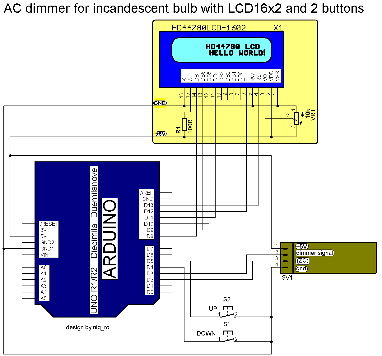
#include <LiquidCrystal.h>
// use LiquidCrystal.h library for alphanumerical display 1602
LiquidCrystal lcd(13,12,11,10,9,8);
/*                                     -------------------
                                       |  LCD  | Arduino |
                                       -------------------
 LCD RS pin to digital pin 13          |  RS   |   D13   |
 LCD Enable pin to digital pin 12      |  E    |   D12   |
 LCD D4 pin to digital pin 11          |  D4   |   D11   |
 LCD D5 pin to digital pin 10          |  D5   |   D10   |
 LCD D6 pin to digital pin 9           |  D6   |    D9   |
 LCD D7 pin to digital pin 8           |  D7   |    D8   |
 LCD R/W pin to ground                 |  R/W  |   GND   |
                                       -------------------
*/

#include <TimerOne.h>           // Avaiable from http://www.arduino.cc/playground/Code/Timer1

volatile int i=0;               // Variable to use as a counter
volatile boolean zero_cross=0;  // Boolean to store a "switch" to tell us if we have crossed zero
int AC_pin = 3;                 // Output to Opto Triac
int buton1 = 4;                 // first button at pin 4
int buton2 = 5;                 // second button at pin 5
int dim2 = 0;                   // led control
int dim = 128;                  // Dimming level (0-128)  0 = on, 128 = 0ff
int pas = 8;                    // step for count;
// version: 4m7 (15.04.2013 - Craiova, Romania) - 16 steps, 4 button & LED blue to red (off to MAX)
// version: 7m3 (22.01.2014 - Craiova, Romania) - 16 steps, 2 button & LCD1602

int freqStep = 75;    // This is the delay-per-brightness step in microseconds.


void setup() {  // Begin setup
  Serial.begin(9600);
  pinMode(buton1, INPUT);  // set buton1 pin as input
  pinMode(buton2, INPUT);  // set buton1 pin as input
  pinMode(AC_pin, OUTPUT);                          // Set the Triac pin as output
  attachInterrupt(0, zero_cross_detect, RISING);    // Attach an Interupt to Pin 2 (interupt 0) for Zero Cross Detection
  Timer1.initialize(freqStep);                      // Initialize TimerOne library for the freq we need
  Timer1.attachInterrupt(dim_check, freqStep);
  // Use the TimerOne Library to attach an interrupt

 lcd.begin(16, 2); // set up the LCD's number of columns and rows:
 lcd.clear(); // clear the screen
 lcd.setCursor(2, 0); // put cursor at colon 0 and row 0
 lcd.print("16 steps AC"); // print a text
 lcd.setCursor(0, 1); // put cursor at colon 0 and row 1
 lcd.print("dimmer for bulb"); // print a text
 delay (3000);
 lcd.clear(); // clear the screen
 lcd.setCursor(1, 0); // put cursor at colon 0 and row 0
 lcd.print("this sketch is"); // print a text
 lcd.setCursor(1, 1); // put cursor at colon 0 and row 1
 lcd.print("made by niq_ro"); // print a text
 delay (3000);
 lcd.clear(); // clear the screen
}

void zero_cross_detect() {
  zero_cross = true;               // set the boolean to true to tell our dimming function that a zero cross has occured
  i=0;
  digitalWrite(AC_pin, LOW);
}

// Turn on the TRIAC at the appropriate time
void dim_check() {
  if(zero_cross == true) {
    if(i>=dim) {
      digitalWrite(AC_pin, HIGH);  // turn on light
      i=0;  // reset time step counter
      zero_cross=false;    // reset zero cross detection
    }
    else {
      i++;  // increment time step counter
    }
  }
}

void loop() {
  digitalWrite(buton1, HIGH);
  digitalWrite(buton2, HIGH);

 if (digitalRead(buton1) == LOW)
   {
  if (dim<127)
  {
    dim = dim + pas;
    if (dim>127)
    {
      dim=127;
    }
  }
   }
  if (digitalRead(buton2) == LOW)
   {
  if (dim>5)
  {
     dim = dim - pas;
  if (dim<0)
    {
      dim=1;
    }
   }
   }
    while (digitalRead(buton1) == LOW) {  }
    delay(10); // waiting little bit...
    while (digitalRead(buton2) == LOW) {  }
    delay(10); // waiting little bit...


  dim2 = 255-2*dim;
  if (dim2<0)
  {
    dim2 = 0;
  }

  Serial.print("dim=");
  Serial.print(dim);

  Serial.print("     dim2=");
  Serial.print(dim2);
  Serial.print("     dim1=");
  Serial.print(2*dim);
  Serial.print('\n');
  delay (100);
 lcd.setCursor(2, 0); // put cursor at colon 0 and row 0
 lcd.print("power is "); // print a text
 lcd.print(100-100*(255-dim2)/255);
 lcd.print("%    "); // print a text
 lcd.setCursor(1, 1); // put cursor at colon 0 and row 1
 lcd.print("dim. level="); // print a text
 lcd.print(dim);
 lcd.print("  "); // print a text
}
    if (dim>127)
    {
      dim=128; // in vechiul sketch era 127
    }
  if (dim<0)
    {
      dim=0;  // in vechiul sketch era 1
    }

/* Photocell simple testing sketch.
Connect one end of the photocell to 5V, the other end to Analog 0.
Then connect one end of a 10K resistor from Analog 0 to ground
For more information see http://learn.adafruit.com/photocells
niq_ro adapted software program in 20.01.2014, see http://nicuflorica.blogspot.com/
*/

#include <LiquidCrystal.h>
// use LiquidCrystal.h library for alphanumerical display 1602
LiquidCrystal lcd(2,3,4,5,6,7);
/*                                    -------------------
                                      |  LCD  | Arduino |
                                      -------------------
 LCD RS pin to digital pin 7          |  RS   |   D7    |
 LCD Enable pin to digital pin 6      |  E    |   D6    |
 LCD D4 pin to digital pin 5          |  D4   |   D5    |
 LCD D5 pin to digital pin 4          |  D5   |   D4    |
 LCD D6 pin to digital pin 3          |  D6   |   D3    |
 LCD D7 pin to digital pin 2          |  D7   |   D2    |
 LCD R/W pin to ground                |  R/W  |   GND   |
                                      -------------------
*/

int photocellPin = 0;     // the cell and 10K pulldown are connected to a0
int photocellReading;     // the analog reading from the analog resistor divider

int relayPin = 9;         // first relay control
int relayPin2 = 8;        // second relay control

void setup(void) {
  // We'll send debugging information via the Serial monitor
  Serial.begin(9600);
  pinMode(relayPin, OUTPUT);  // pin "relayPin" is output pin
  pinMode(relayPin2, OUTPUT);  // pin "relayPin" is output pin

 lcd.begin(16, 2); // set up the LCD's number of columns and rows:
 lcd.clear(); // clear the screen
 lcd.setCursor(0, 0); // put cursor at colon 0 and row 0
 lcd.print("Fotorezistenta"); // print a text
 lcd.setCursor(0, 1); // put cursor at colon 0 and row 1
 lcd.print("comanda 2 relee"); // print a text
 delay (2000);
 lcd.clear(); // clear the screen

 lcd.clear(); // clear the screen
 lcd.setCursor(1, 0); // put cursor at colon 1 and row 0
 lcd.print("Photoresistor"); // print a text
 lcd.setCursor(0, 1); // put cursor at colon 0 and row 1
 lcd.print("control 2 relay"); // print a text
 delay (2000);

 }

void loop(void) {
  digitalWrite(relayPin, HIGH);  // first auxiliar light is off
  digitalWrite(relayPin2, HIGH);  // second auxiliar light is off
  photocellReading = analogRead(photocellPin);

 lcd.clear(); // clear the screen
 if (photocellReading >999)
 {
lcd.setCursor(0, 0); // put cursor at colon 0 and row 0
 }
 else if (photocellReading >99)
 {
lcd.setCursor(1, 0); // put cursor at colon 1 and row 0
 }
 else if (photocellReading >9)
 {
lcd.setCursor(2, 0); // put cursor at colon 2 and row 0
 }
 else
{
lcd.setCursor(3, 0); // put cursor at colon 3 and row 0
 }
 lcd.print(photocellReading); // print a text
 lcd.print(" lx");

  Serial.print(photocellReading);     // the raw analog reading
  Serial.print(" lux");
  // We'll have a few threshholds, qualitatively determined
  if (photocellReading < 20) {
    Serial.println(" - Dark (intuneric)");
    digitalWrite(relayPin, LOW);  // first auxiliar light is on
    digitalWrite(relayPin2, LOW);  // second auxiliar light is on
    Serial.println("All lights are on (Toate luminile sunt aprinse).");
    Serial.println("***********************************************");
  lcd.print(" - Dark");
  lcd.setCursor(2, 1); // put cursor at colon 0 and row 1
  lcd.print("Lights are on");

  } else if (photocellReading < 200) {
    Serial.println(" - Dim (intunecat)");
    digitalWrite(relayPin, LOW);  // first auxiliar light is on
    digitalWrite(relayPin2, HIGH);  // second auxiliar light is off
    Serial.println("First light are on (Un circuit de lumina e aprins).");
    Serial.println("***********************************************");
  lcd.print(" - Dim");
  lcd.setCursor(0, 1); // put cursor at colon 0 and row 1
  lcd.print("1st light are on");

  } else if (photocellReading < 500) {
    Serial.println(" - Light (lumina normala)");
    digitalWrite(relayPin, HIGH);  // first auxiliar light is off
    digitalWrite(relayPin2, HIGH);  // second auxiliar light is off
    Serial.println("All lights are off (Toate luminile sunt stinse).");
    Serial.println("***********************************************");
  lcd.print(" - Light");
  lcd.setCursor(0, 1); // put cursor at colon 0 and row 1
  lcd.print("All lights off!");

  } else if (photocellReading < 800) {
    Serial.println(" - Bright (lumina buna)");
    digitalWrite(relayPin, HIGH);  // first auxiliar light is off
    digitalWrite(relayPin2, HIGH);  // second auxiliar light is off
    Serial.println("All lights are off (Toate luminile sunt stinse).");
    Serial.println("***********************************************");
  lcd.print(" - Bright");
  lcd.setCursor(0, 1); // put cursor at colon 0 and row 1
  lcd.print("All lights off!");

  } else {
    Serial.println(" - Very bright (lumina puternica)");
    digitalWrite(relayPin, HIGH);  // first auxiliar light is off
    digitalWrite(relayPin2, HIGH);  // second auxiliar light is off
    Serial.println("All lights are off (Toate luminile sunt stinse).");
    Serial.println("***********************************************");
  lcd.print("-Dazzling");
  lcd.setCursor(0, 1); // put cursor at colon 0 and row 1
  lcd.print("All lights off!");
  }
  delay(1500);
}


