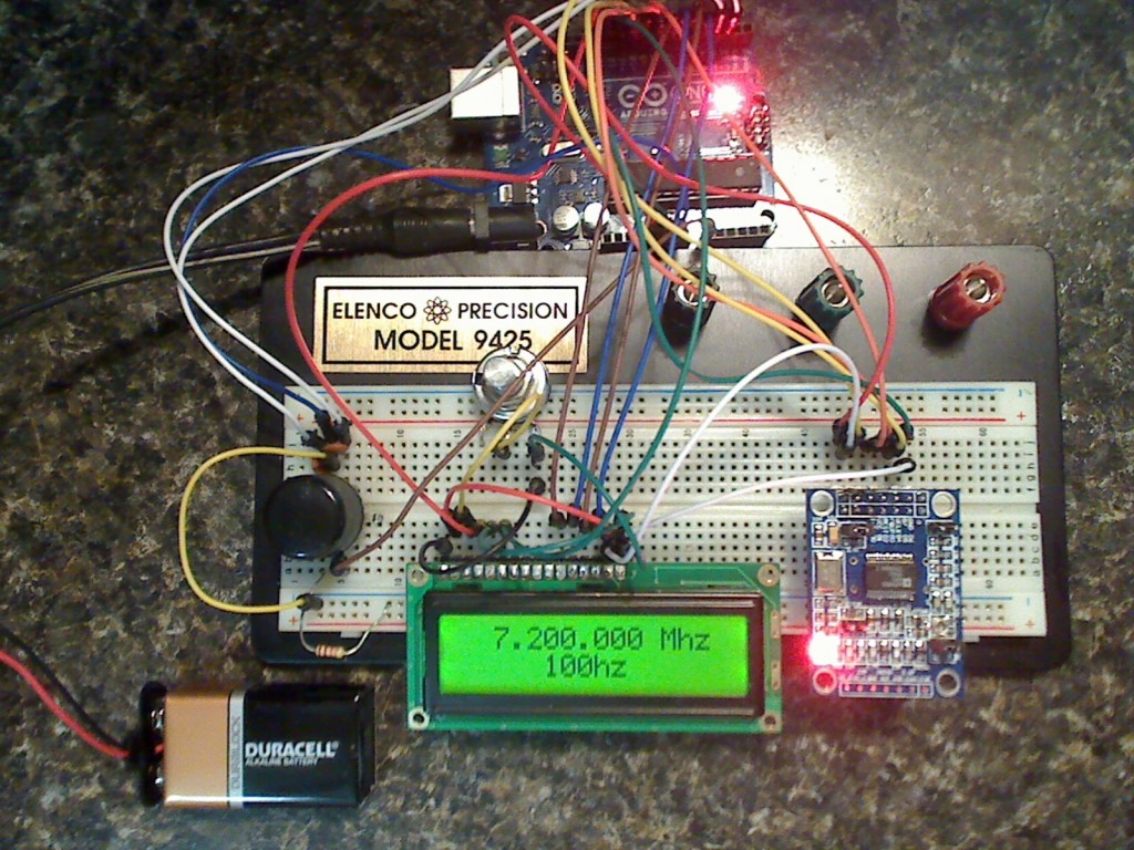
Proiectul, care este baza experimentului, se gaseste la adresa http://www.ad7c.com/projects/ad9850-dds-vfo/ si foloseste memorarea frecventei in EEPROM (la repornire vom avea frecventa memorata):


iar pe una de semnal sinusoidal (dupa ce am umblat la semireglabilul de pe modul, ca nu aparea sinusoida... deci e pun la casa omului un osciloscop):


Pentru a verifica frecventa generata, am folosit o alta placa Arduino cu sketch de frecventmetru (cum este prezentat in articolul de la http://interface.khm.de/index.php/lab/interfaces-advanced/arduino-frequency-counter-library/ si l-am prezentat si eu in articolul Frecventmetru cu.. Arduino:
)


Sketch-ul folosit de mine, cu foarte mici modificari fata de cel original este:
/*
Main code by Richard Visokey AD7C - http://www.ad7c.com
Revision 2.0 - November 6th, 2013
adapted sketch 1.2 - january 1st, 2015 - by Nicu Florica - http://www.tehnic.go.ro
http://nicuflorica.blogspot.ro/
http://arduinotehniq.blogsopt.com/
*/

// Include the library code
#include <LiquidCrystal.h>
#include <rotary.h>
#include <EEPROM.h>

//Setup some items
#define W_CLK 8   // Pin 8 - connect to AD9850 module word load clock pin (CLK)
#define FQ_UD 9   // Pin 9 - connect to freq update pin (FQ)
#define DATA 10   // Pin 10 - connect to serial data load pin (DATA)
#define RESET 11  // Pin 11 - connect to reset pin (RST)
#define pulseHigh(pin) {digitalWrite(pin, HIGH); digitalWrite(pin, LOW); }
Rotary r = Rotary(2,3); // sets the pins the rotary encoder uses.  Must be interrupt pins.
LiquidCrystal lcd(13, 12, 7, 6, 5, 4); // I used an odd pin combination because I need pin 2 and 3 for the interrupts.
int_fast32_t rx=7200000; // Starting frequency of VFO
int_fast32_t rx2=1; // variable to hold the updated frequency
int_fast32_t increment = 1; // starting VFO update increment in HZ.
int buttonstate = 0;
String hertz = "1 Hz";
int  hertzPosition = 6;
byte ones,tens,hundreds,thousands,tenthousands,hundredthousands,millions ;  //Placeholders
String freq; // string to hold the frequency
int_fast32_t timepassed = millis(); // int to hold the arduino miilis since startup
int memstatus = 1;  // value to notify if memory is current or old. 0=old, 1=current.

int ForceFreq = 0;  // Change this to 0 after you upload and run a working sketch to activate the EEPROM memory.  YOU MUST PUT THIS BACK TO 0 AND UPLOAD THE SKETCH AGAIN AFTER STARTING FREQUENCY IS SET!

void setup() {
  pinMode(A0,INPUT); // Connect to a button that goes to GND on push
  digitalWrite(A0,HIGH);
  lcd.begin(16, 2);
  PCICR |= (1 << PCIE2);
  PCMSK2 |= (1 << PCINT18) | (1 << PCINT19);
  sei();
  pinMode(FQ_UD, OUTPUT);
  pinMode(W_CLK, OUTPUT);
  pinMode(DATA, OUTPUT);
  pinMode(RESET, OUTPUT);
  pulseHigh(RESET);
  pulseHigh(W_CLK);
  pulseHigh(FQ_UD);  // this pulse enables serial mode on the AD9850 - Datasheet page 12.
  lcd.setCursor(hertzPosition,1);
  lcd.print(hertz);
   // Load the stored frequency
  if (ForceFreq == 0) {
    freq = String(EEPROM.read(0))+String(EEPROM.read(1))+String(EEPROM.read(2))+String(EEPROM.read(3))+String(EEPROM.read(4))+String(EEPROM.read(5))+String(EEPROM.read(6));
    rx = freq.toInt();
  }
}


void loop() {
  if (rx != rx2){
        showFreq();
        sendFrequency(rx);
        rx2 = rx;
      }

  buttonstate = digitalRead(A0);
  if(buttonstate == LOW) {
        setincrement();
    };

  // Write the frequency to memory if not stored and 2 seconds have passed since the last frequency change.
    if(memstatus == 0){
      if(timepassed+2000 < millis()){
        storeMEM();
        }
      }
}


ISR(PCINT2_vect) {
  unsigned char result = r.process();
  if (result) {
    if (result == DIR_CW){rx=rx+increment;}
    else {rx=rx-increment;};
      if (rx >=30000000){rx=rx2;}; // UPPER VFO LIMIT
      if (rx <=1){rx=rx2;}; // LOWER VFO LIMIT
  }
}


// frequency calc from datasheet page 8 = <sys clock> * <frequency tuning word>/2^32
void sendFrequency(double frequency) {
  int32_t freq = frequency * 4294967295/125000000;  // note 125 MHz clock on 9850.  You can make 'slight' tuning variations here by adjusting the clock frequency.
  for (int b=0; b<4; b++, freq>>=8) {
    tfr_byte(freq & 0xFF);
  }
  tfr_byte(0x000);   // Final control byte, all 0 for 9850 chip
  pulseHigh(FQ_UD);  // Done!  Should see output
}
// transfers a byte, a bit at a time, LSB first to the 9850 via serial DATA line
void tfr_byte(byte data)
{
  for (int i=0; i<8; i++, data>>=1) {
    digitalWrite(DATA, data & 0x01);
    pulseHigh(W_CLK);   //after each bit sent, CLK is pulsed high
  }
}

void setincrement(){
  if(increment == 1){increment = 10; hertz = "10 Hz"; hertzPosition=5;}
  else if(increment == 10){increment = 50; hertz = "50 Hz"; hertzPosition=5;}
  else if (increment == 50){increment = 100;  hertz = "100 Hz"; hertzPosition=4;}
  else if (increment == 100){increment = 500; hertz="500 Hz"; hertzPosition=4;}
  else if (increment == 500){increment = 1000; hertz="1 kHz"; hertzPosition=6;}
  else if (increment == 1000){increment = 2500; hertz="2.5 kHz"; hertzPosition=4;}
  else if (increment == 2500){increment = 5000; hertz="5 kHz"; hertzPosition=6;}
  else if (increment == 5000){increment = 10000; hertz="10 kHz"; hertzPosition=5;}
  else if (increment == 10000){increment = 100000; hertz="100 kHz"; hertzPosition=4;}
  else if (increment == 100000){increment = 1000000; hertz="1 MHz"; hertzPosition=6;}
  else{increment = 1; hertz = "1 Hz"; hertzPosition=6;};
   lcd.setCursor(0,1);
   lcd.print("                ");
   lcd.setCursor(hertzPosition,1);
   lcd.print(hertz);
   delay(250); // Adjust this delay to speed up/slow down the button menu scroll speed.
};

void showFreq(){
    millions = int(rx/1000000);
    hundredthousands = ((rx/100000)%10);
    tenthousands = ((rx/10000)%10);
    thousands = ((rx/1000)%10);
    hundreds = ((rx/100)%10);
    tens = ((rx/10)%10);
    ones = ((rx/1)%10);
    lcd.setCursor(0,0);
    lcd.print("                ");
   if (millions > 9)
   {
       lcd.setCursor(1,0);
      }
   else
   {
        lcd.setCursor(2,0);
   }
    lcd.print(millions);
    lcd.print(",");
    lcd.print(hundredthousands);
    lcd.print(tenthousands);
    lcd.print(thousands);
    lcd.print(".");
    lcd.print(hundreds);
    lcd.print(tens);
    lcd.print(ones);
    lcd.print(" MHz  ");
    timepassed = millis();
    memstatus = 0; // Trigger memory write
};

void storeMEM(){
  //Write each frequency section to a EPROM slot.  Yes, it's cheating but it works!
   EEPROM.write(0,millions);
   EEPROM.write(1,hundredthousands);
   EEPROM.write(2,tenthousands);
   EEPROM.write(3,thousands);
   EEPROM.write(4,hundreds);
   EEPROM.write(5,tens);
   EEPROM.write(6,ones);
   memstatus = 1;  // Let program know memory has been written
   lcd.setCursor(1,15);
   lcd.print("*");
   delay(500);
   lcd.setCursor(1,15);
   lcd.print(" ");

};
- generator de semnal cu AD9850 si reglaj cu encoder rotativ


Buna ziua.
RăspundețiȘtergereAm reusit sa realizez montajul original din http://f5mna.free.fr/ , cu urmatoarele deosebiri:
1. Am folosit AD9851 (foloseste un cuart de 30 MHz cu multiplicare de 6 ori, deci 180 MHz)
2. Schema este putin gresita, in loc de pinul 13 trebuie introdus pinul 12, pentru a se corela cu sketch-ul folosit.
3. Am modificat partea cu butoanele de selectie, deoarece sketch-ul original nu merge. Am folosit sketch-ul de la afisaj pe care l-am introdus ad-literam.
In rest e bine ... functioneaza.
Salut.
RăspundețiȘtergereAm reusit sa procur un modul AD9850 dar din pacate pinii sunt diferiti de ci din modulul tau; pinul DATA nu mai are echivalen?
http://i1247.photobucket.com/albums/gg624/nyplatform1/AD9850-MS-1.jpg
Ma poti ajuta?
Multumesc.