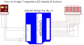
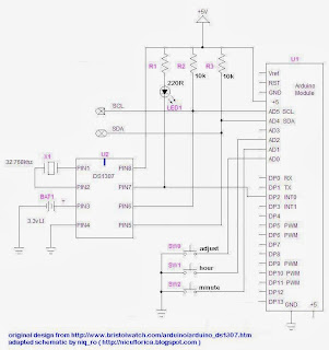
Schema de baza, este aceeasi, doar ca se adauga partea de reglaj (3 butoane, unul cu care se reseteaza datele, unul pentru minute si unul pentru ore). Cand se face reglajul, butonul de resetare date trebuie tinut apasat... partea aceasta am gasit-o la http://www.bristolwatch.com/arduino/arduino_ds1307.htm
Un filmuletul demonstrativ se numeste ceas cu reglaj manual cu Arduino si afisaj LED cu 7 segmente multiplexat, respectiv manual adjust for RTC clock with Arduino and 7-segment LED display (cu tentativa de explicatii in limba engleza):
Sketch-ul este urmatorul:
/*
 4 digit 7 segment display: http://www.sparkfun.com/products/9483
 Datasheet: http://www.sparkfun.com/datasheets/Components/LED/7-Segment/YSD-439AR6B-35.pdf
 7 segments + 4 digits + 1 colon = 12 pins required for full control
 */
// modified connexion by niq_ro from http://nicuflorica.blogspot.com
// for my Luckylight KW4-563ASA
// dataseet: http://www.tme.eu/ro/Document/dfc2efde2e22005fd28615e298ea2655/KW4-563XSA.pdf

int digit1 = 11; //PWM Display pin 12 (digit1 is common anonds A1 from right side)
int digit2 = 10; //PWM Display pin 9 (digit2 is  common A2)
int digit3 = 9; //PWM Display pin 8 (digit3 is common anods A3)
int digit4 = 6; //PWM Display pin 6 (digit4 is common anods, from left side)

//Pin mapping from Arduino to the ATmega DIP28 if you need it
//http://www.arduino.cc/en/Hacking/PinMapping
int segA = 2; //Display pin 11
int segB = 3; //Display pin 7
int segC = 4; //Display pin 4
int segD = 5; //Display pin 2
int segE = 12; //Display pin 1
int segF = 7; //Display pin 10
int segG = 8; //Display pin 5
int segDP = 13; // Display pin 3

#include <Wire.h>
#include "RTClib.h"
RTC_DS1307 RTC;

// Date and time functions using a DS1307 RTC connected via I2C and Wire lib
// original sketck from http://learn.adafruit.com/ds1307-real-time-clock-breakout-board-kit/
// add part with SQW=1Hz from http://tronixstuff.wordpress.com/2010/10/20/tutorial-arduino-and-the-i2c-bus/
// add part with manual adjust http://www.bristolwatch.com/arduino/arduino_ds1307.htm


byte SW0 = A0;
byte SW1 = A1;
byte SW2 = A2;

// use for hexa in zecimal conversion
int zh, uh, ore;
int zm, um, miniti;

void setup() {

 //  Serial.begin(57600);
  Wire.begin();
  RTC.begin();
// RTC.adjust(DateTime(__DATE__, __TIME__));
// if you need set clock... just remove // from line above this

// part code for flashing LED
Wire.beginTransmission(0x68);
Wire.write(0x07); // move pointer to SQW address
// Wire.write(0x00); // turns the SQW pin off
 Wire.write(0x10); // sends 0x10 (hex) 00010000 (binary) to control register - turns on square wave at 1Hz
// Wire.write(0x13); // sends 0x13 (hex) 00010011 (binary) 32kHz

Wire.endTransmission();

  if (! RTC.isrunning()) {
    Serial.println("RTC is NOT running!");
    // following line sets the RTC to the date & time this sketch was compiled
    RTC.adjust(DateTime(__DATE__, __TIME__));
  }


// dht.begin();

  pinMode(segA, OUTPUT);
  pinMode(segB, OUTPUT);
  pinMode(segC, OUTPUT);
  pinMode(segD, OUTPUT);
  pinMode(segE, OUTPUT);
  pinMode(segF, OUTPUT);
  pinMode(segG, OUTPUT);
  pinMode(segDP, OUTPUT);

  pinMode(digit1, OUTPUT);
  pinMode(digit2, OUTPUT);
  pinMode(digit3, OUTPUT);
  pinMode(digit4, OUTPUT);

//  pinMode(13, OUTPUT);

 Serial.begin(9600);
 Serial.println("test for niq_ro");

 pinMode(SW0, INPUT);  // for this use a slide switch
  pinMode(SW1, INPUT);  // N.O. push button switch
  pinMode(SW2, INPUT);  // N.O. push button switch

  digitalWrite(SW0, HIGH); // pull-ups on
  digitalWrite(SW1, HIGH);
  digitalWrite(SW2, HIGH);


}

void loop() {
digitalWrite(segDP, HIGH);
  DateTime now = RTC.now();
  int timp = now.hour()*100+now.minute();
//   int timp = (now.minute(), DEC);
//   displayNumber(12); // this is number to diplay
//   int timp = 1234;
  Serial.print(now.hour(), DEC);
  Serial.print(":");
  Serial.print(now.minute(), DEC);
  Serial.print(" -> ");
  Serial.print(timp);
  Serial.println(" !");

// display parts
   for(int i = 250 ; i >0  ; i--) {
     if (timp >= 1000) displayNumber01(timp);
     else displayNumber02(timp);
   }

   for(int i = 250 ; i >0  ; i--) {
     if (timp >= 1000) displayNumber03(timp);
     else displayNumber04(timp);
   }

  if (!(digitalRead(SW0))) set_time(); // hold the switch to set time
}


void set_time()   {
  byte minutes1 = 0;
  byte hours1 = 0;
  byte minutes = 0;
  byte hours = 0;

  while (!digitalRead(SW0))  // set time switch must be released to exit
  {
    minutes1=minutes;
    hours1=hours;


    while (!digitalRead(SW1)) // set minutes
    {
     minutes++;
   // converting hexa in zecimal:
    zh = hours / 16;
    uh = hours - 16 * zh ;
    ore = 10 * zh + uh;
    zm = minutes / 16;
    um = minutes - 16 * zm ;
    miniti = 10 * zm + um;

     for(int i = 20 ; i >0  ; i--) {
     displayNumber01(ore*100+miniti);
     }


      if ((minutes & 0x0f) > 9) minutes = minutes + 6;
      if (minutes > 0x59) minutes = 0;
      Serial.print("Minutes = ");
      if (minutes >= 9) Serial.print("0");
      Serial.println(minutes, HEX);
    delay(150);
    }

    while (!digitalRead(SW2)) // set hours
    {
     hours++;

   // converting hexa in zecimal:
    zh = hours / 16;
    uh = hours - 16 * zh ;
    ore = 10 * zh + uh;
    zm = minutes / 16;
    um = minutes - 16 * zm ;
    miniti = 10 * zm + um;

     for(int i = 20 ; i >0  ; i--) {
     displayNumber01(ore*100+miniti);
     }


      if ((hours & 0x0f) > 9) hours =  hours + 6;
      if (hours > 0x23) hours = 0;
      Serial.print("Hours = ");
      if (hours <= 9) Serial.print("0");
      Serial.println(hours, HEX);
    delay(150);
    }

    Wire.beginTransmission(0x68); // activate DS1307
    Wire.write(0); // where to begin
    Wire.write(0x00);          //seconds
    Wire.write(minutes);          //minutes
    Wire.write(0x80 | hours);    //hours (24hr time)
    Wire.write(0x06);  // Day 01-07
    Wire.write(0x01);  // Date 0-31
    Wire.write(0x05);  // month 0-12
    Wire.write(0x09);  // Year 00-99
    Wire.write(0x10); // Control 0x10 produces a 1 HZ square wave on pin 7.
    Wire.endTransmission();

    // converting hexa in zecimal:
    zh = hours / 16;
    uh = hours - 16 * zh ;
    ore = 10 * zh + uh;
    zm = minutes / 16;
    um = minutes - 16 * zm ;
    miniti = 10 * zm + um;

     for(int i = 20 ; i >0  ; i--) {
     displayNumber01(ore*100+miniti);
     }
 //  delay(150);

  }

}


void displayNumber01(int toDisplay) {
#define DISPLAY_BRIGHTNESS  500

#define DIGIT_ON  HIGH
#define DIGIT_OFF  LOW

  for(int digit = 4 ; digit > 0 ; digit--) {

    //Turn on a digit for a short amount of time
    switch(digit) {
    case 1:
     digitalWrite(digit1, DIGIT_ON);
     digitalWrite(segDP, HIGH);
      break;
   case 2:
      digitalWrite(digit2, DIGIT_ON);
      digitalWrite(segDP, LOW);
      break;
    case 3:
      digitalWrite(digit3, DIGIT_ON);
      digitalWrite(segDP, HIGH);
      break;
    case 4:
      digitalWrite(digit4, DIGIT_ON);
      digitalWrite(segDP, HIGH);
      break;
    }
    lightNumber(toDisplay % 10);
    toDisplay /= 10;
    delayMicroseconds(DISPLAY_BRIGHTNESS);

     //Turn off all segments
    lightNumber(10);

    //Turn off all digits
    digitalWrite(digit1, DIGIT_OFF);
    digitalWrite(digit2, DIGIT_OFF);
    digitalWrite(digit3, DIGIT_OFF);
    digitalWrite(digit4, DIGIT_OFF);
}
}

void displayNumber02(int toDisplay) {
#define DISPLAY_BRIGHTNESS  500

#define DIGIT_ON  HIGH
#define DIGIT_OFF  LOW

  for(int digit = 4 ; digit > 0 ; digit--) {

    //Turn on a digit for a short amount of time
    switch(digit) {
    case 1:
     lightNumber(10);
     digitalWrite(segDP, HIGH);
     break;
   case 2:
      digitalWrite(digit2, DIGIT_ON);
      digitalWrite(segDP, LOW);
      break;
    case 3:
      digitalWrite(digit3, DIGIT_ON);
      digitalWrite(segDP, HIGH);
      break;
    case 4:
      digitalWrite(digit4, DIGIT_ON);
      digitalWrite(segDP, HIGH);
      break;
    }
    lightNumber(toDisplay % 10);
    toDisplay /= 10;
    delayMicroseconds(DISPLAY_BRIGHTNESS);

     //Turn off all segments
    lightNumber(10);

    //Turn off all digits
    digitalWrite(digit1, DIGIT_OFF);
    digitalWrite(digit2, DIGIT_OFF);
    digitalWrite(digit3, DIGIT_OFF);
    digitalWrite(digit4, DIGIT_OFF);
}
}

void displayNumber03(int toDisplay) {
#define DISPLAY_BRIGHTNESS  500

#define DIGIT_ON  HIGH
#define DIGIT_OFF  LOW

  for(int digit = 4 ; digit > 0 ; digit--) {

    //Turn on a digit for a short amount of time
    switch(digit) {
    case 1:
     digitalWrite(digit1, DIGIT_ON);
     digitalWrite(segDP, HIGH);
      break;
   case 2:
      digitalWrite(digit2, DIGIT_ON);
      digitalWrite(segDP, HIGH);
      break;
    case 3:
      digitalWrite(digit3, DIGIT_ON);
      digitalWrite(segDP, HIGH);
      break;
    case 4:
      digitalWrite(digit4, DIGIT_ON);
      digitalWrite(segDP, HIGH);
      break;
    }
    lightNumber(toDisplay % 10);
    toDisplay /= 10;
    delayMicroseconds(DISPLAY_BRIGHTNESS);

     //Turn off all segments
    lightNumber(10);

    //Turn off all digits
    digitalWrite(digit1, DIGIT_OFF);
    digitalWrite(digit2, DIGIT_OFF);
    digitalWrite(digit3, DIGIT_OFF);
    digitalWrite(digit4, DIGIT_OFF);
}
}

void displayNumber04(int toDisplay) {
#define DISPLAY_BRIGHTNESS  500

#define DIGIT_ON  HIGH
#define DIGIT_OFF  LOW

  for(int digit = 4 ; digit > 0 ; digit--) {

    //Turn on a digit for a short amount of time
    switch(digit) {
    case 1:
     lightNumber(10);
     digitalWrite(segDP, HIGH);
     break;
   case 2:
      digitalWrite(digit2, DIGIT_ON);
      digitalWrite(segDP, HIGH);
      break;
    case 3:
      digitalWrite(digit3, DIGIT_ON);
      digitalWrite(segDP, HIGH);
      break;
    case 4:
      digitalWrite(digit4, DIGIT_ON);
      digitalWrite(segDP, HIGH);
      break;
    }
    lightNumber(toDisplay % 10);
    toDisplay /= 10;
    delayMicroseconds(DISPLAY_BRIGHTNESS);

     //Turn off all segments
    lightNumber(10);

    //Turn off all digits
    digitalWrite(digit1, DIGIT_OFF);
    digitalWrite(digit2, DIGIT_OFF);
    digitalWrite(digit3, DIGIT_OFF);
    digitalWrite(digit4, DIGIT_OFF);
}
}


//Given a number, turns on those segments
//If number == 10, then turn off number
void lightNumber(int numberToDisplay) {

#define SEGMENT_ON  LOW
#define SEGMENT_OFF HIGH

  switch (numberToDisplay){

  case 0:
    digitalWrite(segA, SEGMENT_ON);
    digitalWrite(segB, SEGMENT_ON);
    digitalWrite(segC, SEGMENT_ON);
    digitalWrite(segD, SEGMENT_ON);
    digitalWrite(segE, SEGMENT_ON);
    digitalWrite(segF, SEGMENT_ON);
    digitalWrite(segG, SEGMENT_OFF);
    break;

  case 1:
    digitalWrite(segA, SEGMENT_OFF);
    digitalWrite(segB, SEGMENT_ON);
    digitalWrite(segC, SEGMENT_ON);
    digitalWrite(segD, SEGMENT_OFF);
    digitalWrite(segE, SEGMENT_OFF);
    digitalWrite(segF, SEGMENT_OFF);
    digitalWrite(segG, SEGMENT_OFF);
    break;

  case 2:
    digitalWrite(segA, SEGMENT_ON);
    digitalWrite(segB, SEGMENT_ON);
    digitalWrite(segC, SEGMENT_OFF);
    digitalWrite(segD, SEGMENT_ON);
    digitalWrite(segE, SEGMENT_ON);
    digitalWrite(segF, SEGMENT_OFF);
    digitalWrite(segG, SEGMENT_ON);
    break;

  case 3:
    digitalWrite(segA, SEGMENT_ON);
    digitalWrite(segB, SEGMENT_ON);
    digitalWrite(segC, SEGMENT_ON);
    digitalWrite(segD, SEGMENT_ON);
    digitalWrite(segE, SEGMENT_OFF);
    digitalWrite(segF, SEGMENT_OFF);
    digitalWrite(segG, SEGMENT_ON);
    break;

  case 4:
    digitalWrite(segA, SEGMENT_OFF);
    digitalWrite(segB, SEGMENT_ON);
    digitalWrite(segC, SEGMENT_ON);
    digitalWrite(segD, SEGMENT_OFF);
    digitalWrite(segE, SEGMENT_OFF);
    digitalWrite(segF, SEGMENT_ON);
    digitalWrite(segG, SEGMENT_ON);
    break;

  case 5:
    digitalWrite(segA, SEGMENT_ON);
    digitalWrite(segB, SEGMENT_OFF);
    digitalWrite(segC, SEGMENT_ON);
    digitalWrite(segD, SEGMENT_ON);
    digitalWrite(segE, SEGMENT_OFF);
    digitalWrite(segF, SEGMENT_ON);
    digitalWrite(segG, SEGMENT_ON);
    break;

  case 6:
    digitalWrite(segA, SEGMENT_ON);
    digitalWrite(segB, SEGMENT_OFF);
    digitalWrite(segC, SEGMENT_ON);
    digitalWrite(segD, SEGMENT_ON);
    digitalWrite(segE, SEGMENT_ON);
    digitalWrite(segF, SEGMENT_ON);
    digitalWrite(segG, SEGMENT_ON);
    break;

  case 7:
    digitalWrite(segA, SEGMENT_ON);
    digitalWrite(segB, SEGMENT_ON);
    digitalWrite(segC, SEGMENT_ON);
    digitalWrite(segD, SEGMENT_OFF);
    digitalWrite(segE, SEGMENT_OFF);
    digitalWrite(segF, SEGMENT_OFF);
    digitalWrite(segG, SEGMENT_OFF);
    break;

  case 8:
    digitalWrite(segA, SEGMENT_ON);
    digitalWrite(segB, SEGMENT_ON);
    digitalWrite(segC, SEGMENT_ON);
    digitalWrite(segD, SEGMENT_ON);
    digitalWrite(segE, SEGMENT_ON);
    digitalWrite(segF, SEGMENT_ON);
    digitalWrite(segG, SEGMENT_ON);
    break;

  case 9:
    digitalWrite(segA, SEGMENT_ON);
    digitalWrite(segB, SEGMENT_ON);
    digitalWrite(segC, SEGMENT_ON);
    digitalWrite(segD, SEGMENT_ON);
    digitalWrite(segE, SEGMENT_OFF);
    digitalWrite(segF, SEGMENT_ON);
    digitalWrite(segG, SEGMENT_ON);
    break;

  // all segment are ON
  case 10:
    digitalWrite(segA, SEGMENT_OFF);
    digitalWrite(segB, SEGMENT_OFF);
    digitalWrite(segC, SEGMENT_OFF);
    digitalWrite(segD, SEGMENT_OFF);
    digitalWrite(segE, SEGMENT_OFF);
    digitalWrite(segF, SEGMENT_OFF);
    digitalWrite(segG, SEGMENT_OFF);
    break;

  }
}


Foarte de ajutor articolul acesta de la tine, multumesc. Am observat ca trecerea de la ora 9:59 la ora 10:00 se face afisind 0:00 in loc de 10:00. Dupa un minut, se afiseaza corect 10:01. Cred ca e din cauza ca nu este tratata si situatia cand timp = 1000, e doar timp > 1000
RăspundețiȘtergeremultumesc pentru observatie... am modificat...
ȘtergereHello sir please i need help, why is it when the power of the arduino goes off and come back the time return to 0:00, is there anything i have to do because am using DS1307 rtc
RăspundețiȘtergereand it suppose not to be set again because the rtc is backing it up.
Hello sir thank very much is now working but I won't to know if i can change the 24 hours to 12 hours
RăspundețiȘtergeresir i need to connect seven segment on arduino uno r3 can you give me code and scehamtic please please
RăspundețiȘtergerejust try with R3,.. works fine with all Arduino Uno, Pro Mini, Nano, etc...
ȘtergereSe poate integra reglajul timpului in modul de temperatura si afisaj??
RăspundețiȘtergereAdica http://nicuflorica.blogspot.ro/2013/12/afisaje-led-cu-7-segmente-si-arduino-iv.html si http://nicuflorica.blogspot.ro/2013/07/afisaje-led-cu-7-segmente-si-arduino-ii.html.Ca am reusit doar sa modific pinii si tipul senzorului din DTH11 in DHT22.
ce anume nu face cel de aici si ar trebui sa faca ?
RăspundețiȘtergereAdica sa se poata regla ora si minutele in aceeasi constructie ca si modulul de temperatura si umiditate.
RăspundețiȘtergereSi ma refer la ultima varianta de constructie de pe pagina asta.cea cu butoanele d reglaj al timpului.Multumesc
RăspundețiȘtergereadica sa-i adau senzorul DHT11 (DHT22)? la ceasul cu reglaj?????
RăspundețiȘtergereDa,asta as dori,pentru reglajul timpului ca modulul o sa fie separat de pc.Multumesc pt tot si felicitari pentru aceasta sursa incredibila de informatii pe care de abia o descoper.
RăspundețiȘtergereok, o sa refac montajul si o sa imbunatatesc sketch-urile
ȘtergereMultumesc foarte mult.
RăspundețiȘtergeredaca nu apare pe blog, intr-o saptamana, mai "streseaza-ma" 😎
ȘtergereDa da da, incerc sa imi dau seama unde sa bag rutinele de la dht in codul sursa de ceas cu posibilitatea reglarii.
RăspundețiȘtergereBuna ziua,S-a facut o saptamana, dupa cum ai zis, sa te mai "stresez".Asta daca mai este valabil.Multumesc
RăspundețiȘtergeremai aminteste-mi peste inca una...
ȘtergereOk
Ștergeregata, am pus pe site un articol cu ceasul cu reglaj si cu indicatie de la DHT11: http://nicuflorica.blogspot.ro/2017/08/ceas-cu-reglaj-manual-al-orei.html
Ștergeresi inca o versiune mai ok: http://nicuflorica.blogspot.ro/2017/08/ceas-cu-reglaj-manual-al-orei_11.html
ȘtergereLe am vazut pe amandoua, sunt foarte folositoare.Multumesc pentru tot.
RăspundețiȘtergere