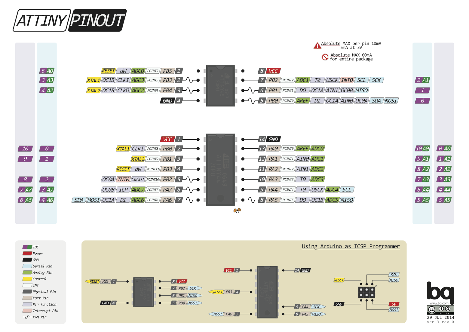
Daca am putut face cu microcontroleul ATtiny85 un termometru dublu cu afisare pe ecran alfanumeric LCD1602 prin intermediul unui registru de deplasare 74HC595, m-am gandit ca pot sa am si indicarea tensiunii bateriei unei masini si astfel sa am indicatii despre temperatura din exterior si cea din interior, asta daca pot folosi pinul fizic 1, RESET, dar si ADC0 (A0), dupa cum e prezentat pe site-ul http://www.pighixxx.com/
In cel mai rau caz, voi renunta la temperatura din interior... Schema gandita de mine deriva din cea a termometrului dublu la care am adaugat un divizor rezistiv cu raport de 1:4 (tensiune maxima de intrare de 20V), cum am facut la indicarul starii bateriei masinii cu led multicolor.
Trebuie sa schimb pictogramele, iar afisarea sa fie ceva de genul:
Pictogramele vor fi de genul:
- baterie:
- temperatura interior (masina):
- temperatura exterior (un copac):
Sketch-ul pe care l-am gandit si de care am fost multumit:
/*this sketch is adapted by niq_ro fromhttp://www.tehnic.go.rohttp://www.niqro.3x.rohttp://nicuflorica.blogspot.ro/http://arduinotehniq.blogspot.com/for made a dual thermometer & battery status for car with ATtiny85 as Arduino.. * 3-pin Arduino interface for HD44780 LCDs via 74HC595 Shift Register * by Rowan Simms code@rowansimms.com * License: Creative Commons - Attribution. * Full Documentation and Description: http://rowansimms.com/article.php/lcd-hookup-in-seconds * * This sketch allows Arduinos to use a shift register to control an LCD, allowing * a reduction in pins it requires from 6 to 3 while still retaining full control * including backlight on/off. * This requires the use of the LiquidCrystal595 library * available at: http://code.google.com/p/arduino-lcd-3pin/ */
#include <LiquidCrystal595.h> // include the library
LiquidCrystal595 lcd(0,1,2); // datapin, latchpin, clockpinbyte baterie1[8] = {
B00000,
B01100,
B11111,
B10000,
B10000,
B10000,
B10000,
B11111,
};
byte baterie2[8] = {
B00000,
B00110,
B11111,
B00001,
B00001,
B00001,
B00001,
B11111,
};
byte masina1[8] = {
B00111,
B01000,
B01111,
B10110,
B10000,
B11111,
B01100,
B01100
};
byte masina2[8] = {
B11100,
B00010,
B11110,
B01101,
B00001,
B11111,
B00110,
B00110
};
byte grad[8] = {
B01110,
B10001,
B10001,
B01110,
B00000,
B00000,
B00000,
};
byte pom1[8] = {
B00111,
B01000,
B10101,
B10010,
B10000,
B01111,
B00001,
B00001
};
byte pom2[8] = {
B11000,
B00110,
B10101,
B01001,
B00010,
B11100,
B10000,
B10000
};
// variables // variabile int t1, t2;
float t10, t20;
float t11, t21;
float t12, t22;
int temperaturePin1 = A0; // output from first LM335 is put at analog input no.0int temperaturePin2 = A3; // output from second LM335 is put at analog input no.1// cei 2 senzori de temperaturia LM335 sunt legati la pinii A0 si A1int divbaterie = A2; //the input pin for voltage dividerint u = 0; // variable to store the value coming from the sensorfloat k=4.90/5; // corection voltage (real voltage after 7805 output)float k1 = k; // real divider correctionfloat u1 = 0; // voltage on batteryfloat divizor = 0.25; // divider raportvoidsetup() {
lcd.begin(16,2); // 16 characters, 2 rows
lcd.createChar(0, grad);
lcd.createChar(1, baterie1);
lcd.createChar(2, baterie2);
lcd.createChar(3, masina1);
lcd.createChar(4, masina2);
lcd.createChar(5, pom1);
lcd.createChar(6, pom2);
lcd.clear(); // clear the screen
lcd.setCursor(2, 0); // put cursor at colon 2 and row 0 = left/up
lcd.print("ATtiny85 dual"); // print a text
lcd.setCursor(2, 1); // put cursor at colon 0 and row 0 = left/down
lcd.print("thermometer +"); // print a textdelay (3000);
lcd.clear(); // clear the screen
lcd.setCursor(0, 0); // put cursor at colon 2 and row 0 = left/up
lcd.print("+ battery status"); // print a text
lcd.setCursor(4, 1); // put cursor at colon 0 and row 0 = left/down
lcd.print("by niq_ro"); // print a textdelay (3000);
lcd.clear(); // clear the screen
}
voidloop() {
// Read and store Sensor Data
t11=0;
t21=0;
//lcd.clear(); // clear the screenfor (int x=1; x <= 5; x++)
{
// calculate the value
t1 = analogRead(temperaturePin1); // read value from temperature from first sensor (LM335);
t10 = 100.0*(k*5.0*t1/1023-2.980)+25.0;
t11 = t10 + t11;
t2 = analogRead(temperaturePin2); // read value from temperature from second sensor (LM335);
t20 = 100.0*(k*5.0*t2/1023-2.980)+25.0;
t21 = t20 + t21;
delay (500);
}
t12 = t11/5.0 -1.5 ; // average and corrected temperature
t22 = t21/5.0 -1.0; // average and corrected temperature
lcd.setCursor(0, 0);
lcd.write(byte(3));
lcd.write(byte(4));
lcd.print(":");
// lcd.print("t1="); if (t12<10) lcd.print(" ");
if (t12>0.0) lcd.print("+");
lcd.print(t12,1);
// lcd.write(0b11011111);
lcd.write(byte(0));
lcd.print("C ");
lcd.setCursor(0, 1);
// lcd.print("ext:");// lcd.print("t2=");
lcd.write(byte(5));
lcd.write(byte(6));
lcd.print(":");
if (t22<10) lcd.print(" ");
if (t22>0.0) lcd.print("+");
lcd.print(t22,1);
// lcd.write(0b11011111);
lcd.write(byte(0));
lcd.print("C ");
// read the value from the sensor:
u = analogRead(divbaterie);
u1 = k1*5.0*u/1023.0; // conver ADC in voltage value
u1 = u1/divizor+0.05;
lcd.setCursor(14, 0);
lcd.write(byte(1));
lcd.write(byte(2));
lcd.setCursor(11, 1);
if (u1<10) lcd.print(" ");
lcd.print(u1,1);
lcd.print("V");
}
Ca marime, el nu este foarte mare fata de cel care avea doar termometru dublu:
Am realizat montajul si am comparat cu un multimetru:
Dupa ce am vazut cum se poate programa un microcontroler ATtiny85 cu sketch Arduino si avand in vedere ca este mai ieftin decat un ATmega328P-PU, poate functiona si fara cuart (oscilator intern la 1MHz), am zis sa fac "ceva" si, avand in vedere ca este iarma si pot fi probleme cu acumulatorul masinii, am facut un indicator pentru starea acumulatorului si pentru alternator si releul regulator. Schema initiala de test a fost cea in care am pus un semireglabil conectat intre +5V si masa, iar cursorul la intrarea analogica:
ulterior am pus si divizorul rezistiv de la intrare:
dar are prea deranjanta cu modul de afisare, asa ca am modificat sketch-ul sa am mai putine situatii si sa am o afisare frumoasa si nederanjanta, facand si schema completa cu alimentarea de la acumulator prin intermediul unui LM7805:
- tensiune pe acumulator mai mica de 10,8V (acumulatorul descarcat... ledul se aprinde cu intermitenta):
- tensiune pe acumulator intre 10,8V si 11,8V (daca motorul este oprit, bateria este destul de descarcata si sunt sanse sa nu porneasca masina, daca tensiunea este cu motorul pornit sunt probleme cu alternatorul si releul regulator, ledul este aprins permanent in rosu):
- tensiune pe acumulator intre 11,8V si 13,5V (daca motorul este oprit, situatia este normala, daca motorul este pornit, bateria poate fi descarcata dupa o perioada de nefolosire sau alternatorul nu incarca suficient, trebuie verificat alternatorul si releul regulator):
- tensiune pe acumulator intre 13,5V si 14,37V (motor pornit, becuri aprinse sau nu, situatia normala, se aprinde doar ledul verde):
- tensiune pe acumulator mai mare de 14,37 (motor pornit, acumulator supravoltat, se aprinde permanent ledul albastru, iar ledul verde se aprinde cu intermitenta, trebuie verificat alternatorul si releul regulator):
Sketch-ul scris de mine pentru schema de mai sus este:
/*basesd sketch named "Analog Input" from Examples -> 03.Analogcreated by David Cuartielles, modified 30 Aug 2011, By Tom Igoehttp://arduino.cc/en/Tutorial/AnalogInput*//* original circuit made by niq_ro from http://www.tehnic.go.rohttp://nicuflorica.blogspot.ro/http://arduinotehniq.blogspot.com/1) uC: ATtiny85 (ATtiny45) at 1MHz (internal clock)2) common chatode RGB LED code OSTA5131A-C, see http://nicuflorica.blogspot.ro/2012/12/arduino-uno-si-un-led-multicolor-rgb.html- an 180ohms resistor at pin D0 (phisical pin 5) in series with RED LED at GND- an 100ohms resistor at pin D1 (phisical pin 6) in series with GREN LED at GND- an 100ohms resistor at pin D2 (phisical pin 7) in series with BLUE LED at GND3) a voltage divisor 1:4 made like this: +BAT --|=10k=|-|=10k=|-|=10k=|-A2|=10k=|-GND, pin A2 is phisical pin 3- for tests can use an 10-50kohms variabile resistor put at +5V and GND, midle at A2 (phisical pin 3)4) Vcc (phisical pin 8) at 5V5) GND (phisixcal pin 4) at GND*/int sensorPin = A2; // select the input pin for the potentiometer / resistor dividerint ledRPin = 0; // select the pin for the RED LEDint ledGPin = 1; // select the pin for the GREEN LEDint ledBPin = 2; // select the pin for the BLUE LEDint u = 0; // variable to store the value coming from the sensorfloat k=4.95/5; // corection voltage// define voltage steps:int treapta1 = 552/k; // Ubat=10,8Vint treapta2 = 604/k; // Ubat=11,8Vint treapta3 = 690/k; // Ubat=13,5Vint treapta4 = 735/k; // Ubat=14,37V (14,4V)voidsetup() {
// declare the ledPins as an OUTPUT:pinMode(ledRPin, OUTPUT);
pinMode(ledGPin, OUTPUT);
pinMode(ledBPin, OUTPUT);
}
voidloop() {
/* // all leds are off digitalWrite(ledRPin, LOW); // turn the red led off digitalWrite(ledGPin, LOW); // turn the green led off digitalWrite(ledBPin, LOW); // turn the blue led off*/// read the value from the sensor:
u = analogRead(sensorPin);
// voltage below 10,8Vif (u < treapta1)
{
digitalWrite(ledGPin, LOW); // turn the green led offdigitalWrite(ledBPin, LOW); // turn the blue led offdigitalWrite(ledRPin, HIGH); // turn the red led ondelay(100);
digitalWrite(ledRPin, LOW); // turn the red led offdelay(100);
digitalWrite(ledRPin, HIGH); // turn the red led ondelay(100);
digitalWrite(ledRPin, LOW); // turn the red led offdelay(1000);
}
// voltage ower 10,8V & below 11,8Vif (u > treapta1 && u < treapta2)
{
digitalWrite(ledGPin, LOW); // turn the green led offdigitalWrite(ledBPin, LOW); // turn the blue led offdigitalWrite(ledRPin, HIGH); // turn the red led ondelay(100);
}
// voltage ower 11,8V & below 13,5Vif (u > treapta2 && u < treapta3)
{
digitalWrite(ledBPin, LOW); // turn the blue led offdigitalWrite(ledRPin, HIGH); // turn the red led ondelay(500);
digitalWrite(ledRPin, LOW); // turn the red led offdelay(100);
digitalWrite(ledGPin, HIGH); // turn the green led ondelay(200);
}
// voltage ower 13,5V & below 14,37Vif (u >= treapta3 && u < treapta4)
{
digitalWrite(ledRPin, LOW); // turn the red led offdigitalWrite(ledBPin, LOW); // turn the blue led offdigitalWrite(ledGPin, HIGH); // turn the green led ondelay(100);
}
// voltage ower 14,37if (u > treapta4)
{
digitalWrite(ledRPin, LOW); // turn the red led offdigitalWrite(ledGPin, HIGH); // turn the green led ondelay(500);
digitalWrite(ledGPin, LOW); // turn the green led offdelay(100);
digitalWrite(ledBPin, HIGH); // turn the blue led ondelay(200);
}
}
Scrierea sketch-ului in microcontrolerul nostru, care poate fi ATTiny85 sau ATtiny45, datorita dimensiunii reduse...