Se afișează postările cu eticheta shield. Afișați toate postările

vineri, 14 noiembrie 2014

Ecran tactil de 2,4" (6cm)

English version: 2.4" touch TFT LCD shield


   Am achizitionat de pe ebay un ecran grafic inclusiv partea de touch rezisitv:
   Desi pe vanzatorul indicata o pagina unde s-ar fi aflat librarii utile si sketch-uri, acestea nu au functionat, asa ca am gasit articolul A 2.4″ TFT TOUCHSCREEN SHIELD FOR ARDUINO de pe site-ul http://www.smokeandwires.co.nz/.
   Ecranul de pe shield are driver-ul ST7781 si pentru a-l face functional, cei de la Smoke and Wires au modificat libraria Adafruit-TFTLCD realizand astfel libraria SWTFT. Aceasta librarie lucreaza impreuna cu libraria Adafruit GFX, iar partea de ecran tactil lucreaza cu libraria Touch-Screen, tot de la Adafruit.
   Primul lucru care m-a deranjat este acela ca foloseste aproape toti pinii lui Arduino Uno, liber este doar A5 pe partea de analogic, iar pe digital doar D0 si D1 sunt liberi, care sunt folositi de interfata USB, de fapt. Dintre acestia, 4 sunt folositi pentru cardul SD (D10, D11, D12 si D13), deci as putea face un shield intermediar pentru a putea folosi acesti pini sau sa-i deconectez mecanic (intrerupere circuite), deoarece ma gandeam sa fac un termostat de centrala cu butoane virtuale...
   Prima data am incarcat sketch-urile din exemplele librariei modificate, facand un filmulet numit afisaj color de 2,4" cu touch rezistiv si Arduino
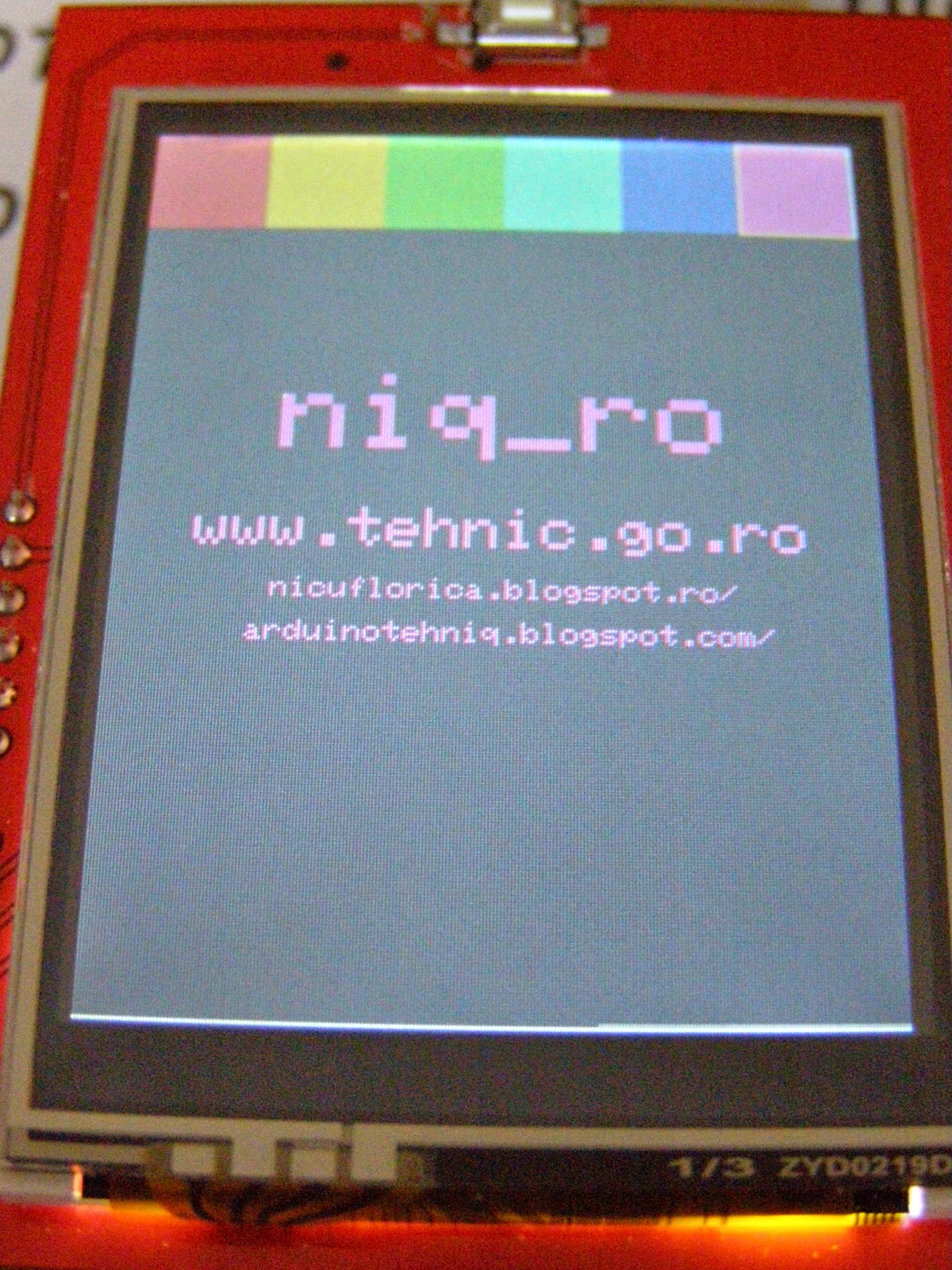
   Am facut si niste poze ale ecranului si a informatiilor de pe el:

   Pentru a intelege sketch-urile si librariile folosite, am inceput sa le fac mici modificari, dupa cum apare in filmuletul afisaj color de 2,4" cu touch rezistiv si Arduino (2)
   Am facut si poze:
   Ulterior, am "intors" ecranul pe "lat" si am obtinut filmuletul afisaj color de 2,4" cu touch rezistiv si Arduino (3)
   Un sketch corectat si cu un buton de stergere in dreapta este:
// Original code provided by Smoke And Wires
// http://www.smokeandwires.co.nz
// This code has been taken from the Adafruit TFT Library and modified
//  by us for use with our TFT Shields / Modules
// For original code / licensing please refer to
// https://github.com/adafruit/TFTLCD-Library

// adapted sketch by niq_ro from http://arduinotehniq.blogspot.com/
// ver. 1m5 - 13.11.2014, Craiova - Romania

#include <Adafruit_GFX.h>    // Core graphics library
#include "SWTFT.h" // Hardware-specific library

// The control pins for the LCD can be assigned to any digital or
// analog pins...but we'll use the analog pins as this allows us to
// double up the pins with the touch screen (see the TFT paint example).
// #define LCD_CS A3 // Chip Select goes to Analog 3
// #define LCD_CD A2 // Command/Data goes to Analog 2
// #define LCD_WR A1 // LCD Write goes to Analog 1
// #define LCD_RD A0 // LCD Read goes to Analog 0

// #define LCD_RESET A4 // Can alternately just connect to Arduino's reset pin

// When using the BREAKOUT BOARD only, use these 8 data lines to the LCD:
// For the Arduino Uno, Duemilanove, Diecimila, etc.:
//   D0 connects to digital pin 8  (Notice these are
//   D1 connects to digital pin 9   NOT in order!)
//   D2 connects to digital pin 2
//   D3 connects to digital pin 3
//   D4 connects to digital pin 4
//   D5 connects to digital pin 5
//   D6 connects to digital pin 6
//   D7 connects to digital pin 7
// For the Arduino Mega, use digital pins 22 through 29
// (on the 2-row header at the end of the board).


#include <Adafruit_GFX.h>    // Core graphics library
#include <SWTFT.h> // Hardware-specific library
#include <TouchScreen.h>


#define YP A1  // must be an analog pin, use "An" notation!
#define XM A2  // must be an analog pin, use "An" notation!
#define YM 7   // can be a digital pin
#define XP 6   // can be a digital pin

#define TS_MINX 150
#define TS_MINY 120
#define TS_MAXX 920
#define TS_MAXY 940

// For better pressure precision, we need to know the resistance
// between X+ and X- Use any multimeter to read it
// For the one we're using, its 300 ohms across the X plate
TouchScreen ts = TouchScreen(XP, YP, XM, YM, 300);


// Assign human-readable names to some common 16-bit color values:
#define BLACK   0x0000
#define BLUE    0x001F
#define RED     0xF800
#define GREEN   0x07E0
#define CYAN    0x07FF
#define MAGENTA 0xF81F
#define YELLOW  0xFFE0
#define WHITE   0xFFFF
//#define ROZ     0xFD20
#define ROZ     0xFBE0
#define GRI     0xBDF7
// http://stackoverflow.com/questions/13720937/c-defined-16bit-high-color
// http://wiibrew.org/wiki/U16_colors

SWTFT tft;

#define BOXSIZE 40
#define PENRADIUS 3
int oldcolor, currentcolor;
int ics; 

void setup(void) {
  Serial.begin(9600);
  Serial.println(F("Paint!"));
  
  tft.reset();
  
  uint16_t identifier = tft.readID();

  Serial.print(F("LCD driver chip: "));
  Serial.println(identifier, HEX);
    

  tft.begin(identifier);

  tft.fillScreen(BLACK);
  tft.fillRect(0, 0, 320, 240, BLACK);
  tft.setRotation(3);
  tft.setCursor(30, 100);
  tft.setTextColor(RED);  tft.setTextSize(3);
  tft.println("LCD driver chip: ");
  tft.setCursor(100, 150);
  tft.setTextColor(BLUE);
  tft.println(identifier, HEX);

delay(2000);
tft.fillRect(0, 0, 320, 240, BLACK);
  
tft.setRotation(0);
  tft.fillRect(0, 0, BOXSIZE, BOXSIZE, RED);
  tft.fillRect(0, BOXSIZE, BOXSIZE, BOXSIZE, YELLOW);
  tft.fillRect(0, BOXSIZE*2, BOXSIZE, BOXSIZE, GREEN);
  tft.fillRect(0, BOXSIZE*3, BOXSIZE, BOXSIZE, CYAN);
  tft.fillRect(0, BOXSIZE*4, BOXSIZE, BOXSIZE, BLUE);
  tft.fillRect(0, BOXSIZE*5, BOXSIZE, BOXSIZE, MAGENTA);
  tft.fillRect(0, BOXSIZE*6, BOXSIZE, BOXSIZE, GRI);
  tft.fillRect(0, BOXSIZE*7, BOXSIZE, BOXSIZE,  ROZ);
//tft.fillRect(BOXSIZE, BOXSIZE, BOXSIZE, BOXSIZE, WHITE);
 
  tft.drawRect(0, 0, BOXSIZE, BOXSIZE, WHITE);
  currentcolor = RED;


 cifre (WHITE);
  pinMode(13, OUTPUT);
}

#define MINPRESSURE 10
#define MAXPRESSURE 1000

void loop()
{
  digitalWrite(13, HIGH);
  // Recently Point was renamed TSPoint in the TouchScreen library
  // If you are using an older version of the library, use the
  // commented definition instead.
  // Point p = ts.getPoint();
  TSPoint p = ts.getPoint();
  digitalWrite(13, LOW);

  // if sharing pins, you'll need to fix the directions of the touchscreen pins
  //pinMode(XP, OUTPUT);
  pinMode(XM, OUTPUT);
  pinMode(YP, OUTPUT);
  //pinMode(YM, OUTPUT);

  // we have some minimum pressure we consider 'valid'
  // pressure of 0 means no pressing!

  if (p.z > MINPRESSURE && p.z < MAXPRESSURE) {
  /*  
    Serial.print("X = "); Serial.print(p.x);
    Serial.print("\tY = "); Serial.print(p.y);
    Serial.print("\tPressure = "); Serial.println(p.z);
  */      
if (p.y < (TS_MINY-5)) stergere();
    // scale from 0->1023 to tft.width
    p.x = tft.width()-(map(p.x, TS_MINX, TS_MAXX, tft.width(), 0));
    p.y = tft.height()-(map(p.y, TS_MINY, TS_MAXY, tft.height(), 0));
  /*  
    Serial.print("("); Serial.print(p.x);
    Serial.print(", "); Serial.print(p.y);
    Serial.println(")");
  */  
    if (p.x < BOXSIZE) {
       oldcolor = currentcolor;

       if (p.y < BOXSIZE) { 
         currentcolor = RED; 
         tft.drawRect(0, 0, BOXSIZE, BOXSIZE, WHITE); 
//         text (currentcolor);
       } else if (p.y < BOXSIZE*2) {
         currentcolor = YELLOW;
         tft.drawRect(0, BOXSIZE, BOXSIZE, BOXSIZE, WHITE);
//         text (currentcolor);
       } else if (p.y < BOXSIZE*3) {
         currentcolor = GREEN;
         tft.drawRect(0, BOXSIZE*2, BOXSIZE, BOXSIZE, WHITE);
//         text (currentcolor);
       } else if (p.y < BOXSIZE*4) {
         currentcolor = CYAN;
         tft.drawRect(0, BOXSIZE*3, BOXSIZE, BOXSIZE, WHITE);       
//         text (currentcolor);
       } else if (p.y < BOXSIZE*5) {
         currentcolor = BLUE;
         tft.drawRect(0, BOXSIZE*4, BOXSIZE, BOXSIZE, WHITE);        
//         text (currentcolor);
       } else if (p.y < BOXSIZE*6) {
         currentcolor = MAGENTA;
         tft.drawRect(0,BOXSIZE*5, BOXSIZE, BOXSIZE, WHITE);        
//         text (currentcolor);
       } else if (p.y < BOXSIZE*7) {
         currentcolor = GRI;
         tft.drawRect(0,BOXSIZE*6, BOXSIZE, BOXSIZE, WHITE);        
//         text (currentcolor);
       } else if (p.y < BOXSIZE*8) {
         currentcolor = ROZ;
         tft.drawRect(0,BOXSIZE*7, BOXSIZE, BOXSIZE, WHITE);
         stergere();        
       }

text (currentcolor);
//cifre (currentcolor);
       if (oldcolor != currentcolor) {
          if (oldcolor == RED) tft.fillRect(0, 0, BOXSIZE, BOXSIZE, RED);
          if (oldcolor == YELLOW) tft.fillRect(0, BOXSIZE, BOXSIZE, BOXSIZE, YELLOW);
          if (oldcolor == GREEN) tft.fillRect(0, BOXSIZE*2, BOXSIZE, BOXSIZE, GREEN);
          if (oldcolor == CYAN) tft.fillRect(0, BOXSIZE*3, BOXSIZE, BOXSIZE, CYAN);
          if (oldcolor == BLUE) tft.fillRect(0, BOXSIZE*4, BOXSIZE, BOXSIZE, BLUE);
          if (oldcolor == MAGENTA) tft.fillRect(0, BOXSIZE*5, BOXSIZE, BOXSIZE, MAGENTA);
          if (oldcolor == GRI) tft.fillRect(0, BOXSIZE*6, BOXSIZE, BOXSIZE, GRI);
          if (oldcolor == ROZ) tft.fillRect(0, BOXSIZE*7, BOXSIZE, BOXSIZE, ROZ);
     cifre (currentcolor);  
     }
      
    }
   // if (((p.y-PENRADIUS) > BOXSIZE) && ((p.y+PENRADIUS) < tft.height())) {
/*
if (((p.y-PENRADIUS) > 5) && ((p.y+PENRADIUS) < tft.height())) {
   tft.fillCircle(p.x, p.y, PENRADIUS, currentcolor);
    }
*/
if (((p.x-PENRADIUS) > BOXSIZE) && ((p.x+PENRADIUS) < tft.width())) {
   tft.fillCircle(p.x, p.y, PENRADIUS, currentcolor);
    }

  }
}

void text (int culoare) 
{
tft.setRotation(3);
tft.setCursor(70, 80);
          tft.setTextColor(culoare);  tft.setTextSize(5);
 /*         tft.println("niq_ro");
          tft.setCursor(12, 130); tft.setTextSize(3);
          tft.println("www.tehnic.go.ro");
          tft.setCursor(20, 165); tft.setTextSize(2);
          tft.println("nicuflorica.blogspot.ro");
*/
          tft.setCursor(5, 220); tft.setTextSize(2);
          tft.println("arduinotehniq.blogspot.com");
tft.setRotation(0);
}

void cifre (int culoare)
{
// number for "buttons"
 tft.setRotation(3);
 tft.setTextColor(culoare);
 tft.setTextSize(3);
 tft.drawLine(0, 0, 40, 40, culoare);
 tft.drawLine(0, 40, 40, 0, culoare);
// tft.setCursor(15, 10);
// tft.println("1");
 tft.setCursor(55, 10);
 tft.println("1");
 tft.setCursor(95, 10);
 tft.println("2");
 tft.setCursor(135, 10);
 tft.println("3");
 tft.setCursor(175, 10);
 tft.println("4");
 tft.setCursor(215, 10);
 tft.println("5");
 tft.setCursor(255, 10);
 tft.println("6");
 tft.setCursor(295, 10);
 tft.println("7");
  
 tft.setRotation(0);
}

void stergere ()
{
      Serial.println("erase");
      // press the bottom of the screen to erase 
 //     tft.fillRect(0, BOXSIZE, tft.width(), tft.height()-BOXSIZE, BLACK);
   tft.fillRect(0, 0, 240, 320, BLACK);
   tft.setRotation(0);
  tft.fillRect(0, 0, BOXSIZE, BOXSIZE, RED);
  tft.fillRect(0, BOXSIZE, BOXSIZE, BOXSIZE, YELLOW);
  tft.fillRect(0, BOXSIZE*2, BOXSIZE, BOXSIZE, GREEN);
  tft.fillRect(0, BOXSIZE*3, BOXSIZE, BOXSIZE, CYAN);
  tft.fillRect(0, BOXSIZE*4, BOXSIZE, BOXSIZE, BLUE);
  tft.fillRect(0, BOXSIZE*5, BOXSIZE, BOXSIZE, MAGENTA);
  tft.fillRect(0, BOXSIZE*6, BOXSIZE, BOXSIZE, GRI);
  tft.fillRect(0, BOXSIZE*7, BOXSIZE, BOXSIZE,  ROZ);
//tft.fillRect(BOXSIZE, BOXSIZE, BOXSIZE, BOXSIZE, WHITE);
 
  tft.drawRect(0, 0, BOXSIZE, BOXSIZE, WHITE);
  currentcolor = RED;
     cifre (WHITE);  
    }
   De data aceasta, apare ecranul liber pentru desenare:
   Am facut si un filmulet numit afisaj color de 2,4" cu touch rezistiv si Arduino (4) care prezinta modul de comportare al programului si ce se poate face cu el:

marți, 16 aprilie 2013

Variator de tensiune pentru bec cu Arduino (IV)

  Am revenit la partea de variator de tensiune pentru bec cu incandescenta (adica ac light dimmer) cu documentatia prezentata la DXARTS, de data asta cu controlul intensitatii becului alimentat la retea (230V) cu un potentiometru.

/*
AC Light Control

 Updated by Robert Twomey <rtwomey@u.washington.edu>

 Changed zero-crossing detection to look for RISING edge rather
 than falling.  (originally it was only chopping the negative half
 of the AC wave form). 

 Also changed the dim_check() to turn on the Triac, leaving it on 
 until the zero_cross_detect() turn's it off.

 Ryan McLaughlin <ryanjmclaughlin@gmail.com>

 The hardware consists of an Triac to act as an A/C switch and 
 an opto-isolator to give us a zero-crossing reference.
 The software uses two interrupts to control dimming of the light.
 The first is a hardware interrupt to detect the zero-cross of
 the AC sine wave, the second is software based and always running 
 at 1/128 of the AC wave speed. After the zero-cross is detected 
 the function check to make sure the proper dimming level has been 
 reached and the light is turned on mid-wave, only providing 
 partial current and therefore dimming our AC load.

 Thanks to http://www.andrewkilpatrick.org/blog/?page_id=445 
 and http://www.hoelscher-hi.de/hendrik/english/dimmer.htm

 */

#include <TimerOne.h>           // Avaiable from http://www.arduino.cc/playground/Code/Timer1

volatile int i=0;               // Variable to use as a counter
volatile boolean zero_cross=0;  // Boolean to store a "switch" to tell us if we have crossed zero
int AC_pin = 3;                // Output to Opto Triac
int POT_pin = A3;             // Pot for testing the dimming
int LED = 11;                    // LED for testing
int dim = 0;                    // Dimming level (0-128)  0 = on, 128 = 0ff

int freqStep = 75;    // This is the delay-per-brightness step in microseconds.
// It is calculated based on the frequency of your voltage supply (50Hz or 60Hz)
// and the number of brightness steps you want. 
// 
// The only tricky part is that the chopper circuit chops the AC wave twice per
// cycle, once on the positive half and once at the negative half. This meeans
// the chopping happens at 120Hz for a 60Hz supply or 100Hz for a 50Hz supply. 

// To calculate freqStep you divide the length of one full half-wave of the power
// cycle (in microseconds) by the number of brightness steps. 
//
// (1000000 uS / 120 Hz) / 128 brightness steps = 65 uS / brightness step
//
// 1000000 us / 120 Hz = 8333 uS, length of one half-wave.

void setup() {                                      // Begin setup
  pinMode(AC_pin, OUTPUT);                          // Set the Triac pin as output
  pinMode(LED, OUTPUT);                             // Set the LED pin as output
  attachInterrupt(0, zero_cross_detect, RISING);   // Attach an Interupt to Pin 2 (interupt 0) for Zero Cross Detection
  Timer1.initialize(freqStep);                      // Initialize TimerOne library for the freq we need
  Timer1.attachInterrupt(dim_check, freqStep);      
  // Use the TimerOne Library to attach an interrupt
  // to the function we use to check to see if it is 
  // the right time to fire the triac.  This function 
  // will now run every freqStep in microseconds.                                            
}

void zero_cross_detect() {    
  zero_cross = true;               // set the boolean to true to tell our dimming function that a zero cross has occured
  i=0;
  digitalWrite(AC_pin, LOW);
}                                 

// Turn on the TRIAC at the appropriate time
void dim_check() {                   
  if(zero_cross == true) {              
    if(i>=dim) {                     
      digitalWrite(AC_pin, HIGH);  // turn on light       
      i=0;  // reset time step counter                         
      zero_cross=false;    // reset zero cross detection
    } 
    else {
      i++;  // increment time step counter                     
    }                                
  }                                  
}                                      

void loop() {                        
  dim = analogRead(POT_pin) / 8;  // read dimmer value from potentiometer
  analogWrite(LED, dim);  // write dimmer value to the LED, for debugging
}


   Cateva stari ale intensitatii becului:
 

   Un filmulet cu functionarea acestui variator de tensiune pentru bec comandat de un potentiometru se numeste ac light dimmer with Arduino (XIII):
   Al doilea sketch pe care l-am folosit folosesc 2 LED-uri din cele 3 ale LED-lui multicolor pentru a prezenta starea becului, doar LED-ul albastru aprins indica bec stins, iar doar LED-ul rosu aprins indica bec aprins la intensitate maxima:

/*
AC Light Control
 Updated by Robert Twomey <rtwomey@u.washington.edu>
 Ryan McLaughlin <ryanjmclaughlin@gmail.com>
 Thanks to http://www.andrewkilpatrick.org/blog/?page_id=445 
 and http://www.hoelscher-hi.de/hendrik/english/dimmer.htm
 modified sketch by niq_ro from http://www.tehnic.go.ro &
 http://www.nicuflorica.blogspot.com
 version 1m2 - 15.04.2013

 */
#include <TimerOne.h>           // Avaiable from http://www.arduino.cc/playground/Code/Timer1

volatile int i=0;               // Variable to use as a counter
volatile boolean zero_cross=0;  // Boolean to store a "switch" to tell us if we have crossed zero
int AC_pin = 3;                // Output to Opto Triac
int POT_pin = A3;             // Pot for testing the dimming
int LED = 10;                    // LED for testing
int LED2 =11;                    // second LED
int dim = 0;                    // Dimming level (0-128)  0 = on, 128 = 0ff

int freqStep = 75;    // This is the delay-per-brightness step in microseconds (for 50Hz)

void setup() {                                      // Begin setup
  pinMode(AC_pin, OUTPUT);                          // Set the Triac pin as output
  pinMode(LED, OUTPUT);                             // Set the LED pin as output
  pinMode(LED2, OUTPUT);                            // Set the LED2 pin as output
  attachInterrupt(0, zero_cross_detect, RISING);   // Attach an Interupt to Pin 2 (interupt 0) for Zero Cross Detection
  Timer1.initialize(freqStep);                      // Initialize TimerOne library for the freq we need
  Timer1.attachInterrupt(dim_check, freqStep);      
  // Use the TimerOne Library to attach an interrupt
  // to the function we use to check to see if it is 
  // the right time to fire the triac.  This function 
  // will now run every freqStep in microseconds.                                            
}

void zero_cross_detect() {    
  zero_cross = true;               // set the boolean to true to tell our dimming function that a zero cross has occured
  i=0;
  digitalWrite(AC_pin, LOW);
}                                 

// Turn on the TRIAC at the appropriate time
void dim_check() {                   
  if(zero_cross == true) {              
    if(i>=dim) {                     
      digitalWrite(AC_pin, HIGH);  // turn on light       
      i=0;  // reset time step counter                         
      zero_cross=false;    // reset zero cross detection
    } 
    else {
      i++;  // increment time step counter                     
    }                                
  }                                  
}                                      

void loop() {                        
  dim = analogRead(POT_pin) / 8;  // read dimmer value from potentiometer
  analogWrite(LED, dim);  // write dimmer value to the LED, for debugging
  analogWrite(LED2, 255-2*dim);  // write dimmer value to the second LED, for debugging
}

    Cateva poze:
   Un filmulet cu functionarea acestui variator de tensiune pentru bec comandat de un potentiometru se numeste ac light dimmer with Arduino (XIV):
    Revenind la partea de butoane, vom folosi 4....
sketch-ul este:


/*
AC Light Control
 Updated by Robert Twomey <rtwomey@u.washington.edu>
 Thanks to http://www.andrewkilpatrick.org/blog/?page_id=445 
 and http://www.hoelscher-hi.de/hendrik/english/dimmer.htm
 adapted sketch by niq_ro from
 http://www.tehnic.go.ro 
 http://www.niqro.3x.ro 
 http://nicuflorica.blogspot.com 
*/

#include <TimerOne.h>           // Avaiable from http://www.arduino.cc/playground/Code/Timer1

volatile int i=0;               // Variable to use as a counter
volatile boolean zero_cross=0;  // Boolean to store a "switch" to tell us if we have crossed zero
int AC_pin = 3;                 // Output to Opto Triac
int buton1 = 4;                 // first button at pin 4
int buton2 = 5;                 // second button at pin 5
int buton3 = 6;                 // second button at pin 6
int buton4 = 7;                 // second button at pin 7
int redLED = 11;                // red LED at pin 11 
int greenLED = 9;               // green LED at pin 9
int blueLED = 10;               // blue LED at pin 10
int dim2 = 0;                   // led control
int dim = 128;                  // Dimming level (0-128)  0 = on, 128 = 0ff
int pas = 8;                    // step for count;
// version: 4m7 (15.04.2013 - Craiova, Romania) - 16 steps, 4 button & LED blue to red (off to MAX) 

int freqStep = 75;    // This is the delay-per-brightness step in microseconds.

void setup() {  // Begin setup
  Serial.begin(9600);   
  pinMode(buton1, INPUT);  // set buton1 pin as input
  pinMode(AC_pin, OUTPUT);                          // Set the Triac pin as output
  pinMode(redLED, OUTPUT);                          // Set the LED pin as output
  pinMode(greenLED, OUTPUT);                        // Set the LED pin as output
  pinMode(blueLED, OUTPUT);                         // Set the LED pin as output
  attachInterrupt(0, zero_cross_detect, RISING);    // Attach an Interupt to Pin 2 (interupt 0) for Zero Cross Detection
  Timer1.initialize(freqStep);                      // Initialize TimerOne library for the freq we need
  Timer1.attachInterrupt(dim_check, freqStep);      
  // Use the TimerOne Library to attach an interrupt
}

void zero_cross_detect() {    
  zero_cross = true;               // set the boolean to true to tell our dimming function that a zero cross has occured
  i=0;
  digitalWrite(AC_pin, LOW);
}                                 

// Turn on the TRIAC at the appropriate time
void dim_check() {                   
  if(zero_cross == true) {              
    if(i>=dim) {                     
      digitalWrite(AC_pin, HIGH);  // turn on light       
      i=0;  // reset time step counter                         
      zero_cross=false;    // reset zero cross detection
    } 
    else {
      i++;  // increment time step counter                     
    }                                
  }                                  
}                                      

void loop() {                        
  if (digitalRead(buton3) == LOW)   
   {
  dim = 0;
  }
  if (digitalRead(buton4) == LOW)   
   {
  dim = 127;
  }

  if (digitalRead(buton1) == LOW)   
   {
  if (dim<127)  
  {
    dim = dim + pas;
    if (dim>127) 
    {
      dim=127;
    }
  }
  else
  {
   analogWrite(greenLED, 255);  // LED is ON for indicate an error
  delay (100);
   analogWrite(greenLED, 0);  // LED is now OFF
   }
   }
  if (digitalRead(buton2) == LOW)   
   {
  if (dim>5)  
  {
     dim = dim - pas;
  if (dim<0) 
    {
      dim=1;
    }
   }
  else
  {
  analogWrite(greenLED, 255);  // LED is ON for indicate an error
  delay (100);   
  analogWrite(greenLED, 0);    // LED is now OFF
   }
   }
    while (digitalRead(buton1) == LOW) {  }              
    delay(10); // waiting little bit...  
    while (digitalRead(buton2) == LOW) {  }              
    delay(10); // waiting little bit...    
           
  analogWrite(blueLED, 2*dim);  // write dimmer value to the LED, for debugging
  dim2 = 255-2*dim;
  if (dim2<0)
  {
    dim2 = 0;
  }
  analogWrite(redLED, dim2);  // write dimmer value to the LED, for debugging

  Serial.print("dim=");
  Serial.print(dim);

  Serial.print("     dim2=");
  Serial.print(dim2);
  Serial.print("     dim1=");
  Serial.print(2*dim);
  Serial.print('\n');
  delay (100);
}

  Un filmulet cu functionarea acestui variator de tensiune pentru bec comandat de un potentiometru se numeste ac light dimmer with Arduino (XV):