
Din pacate, informatiile nu mai sunt disponibile pe acel site, asa ca am cautat locuri unde a mai fost prezentat acest dispozitiv si am gasit urmatoarele materiale la:
- http://black-electronics.com/blog/transistor-tester/
- http://robocraft.ru/blog/projects/2998.html


- http://forum.arduino.cc/index.php?topic=164112.0
unde gasit o colectie de sketch-uri;
- http://arduinows.blogspot.ro/2014/06/ardutester-een-electronische.html
/*
___ ___ _____ ___ ___ ___ ___ ___
/ /\ / /\ / /::\ /__/\ ___ / /\ / /\ ___ / /\ / /\
/ /::\ / /::\ / /:/\:\ \ \:\ / /\ / /:/_ / /:/_ / /\ / /:/_ / /::\
/ /:/\:\ / /:/\:\ / /:/ \:\ \ \:\ / /:/ / /:/ /\ / /:/ /\ / /:/ / /:/ /\ / /:/\:\
/ /:/~/::\ / /:/~/:/ /__/:/ \__\:| ___ \ \:\ / /:/ / /:/ /:/_ / /:/ /::\ / /:/ / /:/ /:/_ / /:/~/:/
/__/:/ /:/\:\ /__/:/ /:/___ \ \:\ / /:/ /__/\ \__\:\ / /::\ /__/:/ /:/ /\ /__/:/ /:/\:\ / /::\ /__/:/ /:/ /\ /__/:/ /:/___
\ \:\/:/__\/ \ \:\/:::::/ \ \:\ /:/ \ \:\ / /:/ /__/:/\:\ \ \:\/:/ /:/ \ \:\/:/~/:/ /__/:/\:\ \ \:\/:/ /:/ \ \:\/:::::/
\ \::/ \ \::/~~~~ \ \:\/:/ \ \:\ /:/ \__\/ \:\ \ \::/ /:/ \ \::/ /:/ \__\/ \:\ \ \::/ /:/ \ \::/~~~~
\ \:\ \ \:\ \ \::/ \ \:\/:/ \ \:\ \ \:\/:/ \__\/ /:/ \ \:\ \ \:\/:/ \ \:\
\ \:\ \ \:\ \__\/ \ \::/ \__\/ \ \::/ /__/:/ \__\/ \ \::/ \ \:\
\__\/ \__\/ \__\/ \__\/ \__\/ \__\/ \__\/
ARDUTESTER v0.X 25/04/2013
Original Source from: http://www.mikrocontroller.net/articles/AVR-Transistortester
Original Software: by Karl-Heinz Kuebbeler (kh_kuebbeler@web.de)
The Ardutester software is based on porting by Markus Reschke (madires@theca-tabellaria.de)
Schematic & Home Page: http://www.pighixxx.com/lavori/ardutester/
Arduino version: PighiXXX (info@pighixxx.com)
PaoloP (http://www.arduino.cc/forum/index.php?action=profile;u=58300)
- ONLY TTL COMPONENTS!
TODO:
- Detailed Component Analysis
CHANGELOG:
- 01/05/2013 v06e - Waitus Function, String to Flash Functions, Killed 3 Goto :-), Code Cleanup - PighiXXX
- 01/05/2013 v06f - Killed all Goto (Thanks to PaoloP), Implemented Button
- 01/05/2013 v06g - Code Cleanup
- 02/05/2013 v06h - Code Cleanup, SERIAL-LCD Flag, I2C LCD Functions
- 02/05/2013 v06i - Button Flag, Button Function
- 02/05/2013 v06j - PowerSave Function, Code Cleanup, Flag only when more info
- 02/05/2013 v06k - Some fix (By PaoloP)
- 03/05/2013 v06l - Disabled digital input on analog pins (By PaoloP), Minor fixes
- 04/05/2013 v06m - ShowFET() fixed, Code Cleanup, Short Circuit Ok
- 05/05/2013 v06n - CheckResistor Function Ok
- 06/05/2013 v06o - SelfTest Function (v0.3), SelfAdjust, Minor fixes
- 21/05/2013 v06p - Add LCD no I2C, Removed Leonardo support: this sketch work only on ATmega328. (By PaoloP)
- 07/06/2013 v06q - ArduTester Software Client Functions (By PighiXXX)
- 08/07/2013 v07a - SmallResistor() fixes, Inductance Measurement, Leakage Current Measurement, BJT functions fixed, Minor fixes (By PighiXXX)
TODO ReCheck Print Functions & LCD Functions - This is an alpha version! Lightless version!
- 17/07/2013 v07b - MOSFETs function fixed, Minor fixes, Show Functions revisited, I2C LCD Deprecated, Deep debug :-)
Button Function revisited, PWM Tool, Serial Menu, AutoAdjust, EEProm functions (By PighiXXX)
- 21/07/2013 v07c Some fix (By PaoloP), LCD Functions revisited (By PighiXXX)
- 22/07/2013 v07d LCDMenu, Some fix (By PighiXXX)
- 23/07/2013 v07e SetDefault function, Some fix, selFreq optimized, TestKey improvements, Client support (By PighiXXX)
TWI, SPI, TIMER2 disabled (By PaoloP)
- 25/07/2013 v07f ReadU function revisited (By PaoloP), Some fix (By PaoloP & PighiXXX)
*/
//WorkAround for IDE ifndef bug
char foo;
//ARDUTESTER FEATURES
//Remember LCD_PRINT or DEBUG_PRINT
#define BUTTON_INST //Button Installed
#define LCD_PRINT //Print on LCD
//Remember DEBUG_PRINT or ATSW
//#define ATSW //ArduTester Software Client Enabled
//#define DEBUG_PRINT //Print on Serial Port
#define DET_COMP_ANALYSIS //Detailed Component Analysis (Soon)
#define TIMEOUT_BL 600 //LCD Backlight Timeout
#define LONG_PRESS 26 //Button Long Press
#define USER_WAIT 3000 //Nexpage Timeout
//Check features
#if not defined(__AVR_ATmega328P__)
#error Sorry, this program works only on Arduino Uno
#endif
#if defined(LCD_PRINT) && defined(DEBUG_PRINT)
#error Invalid Parameters: Use LCD_PRINT or DEBUG_PRINT
#endif
#if defined(DEBUG_PRINT) && defined(ATSW)
#error Invalid Parameters: Use DEBUG_PRINT or ATSW
#endif
//Includes
#include <avr/wdt.h>
#include <avr/sleep.h>
#include <avr/power.h>
#include <EEPROM.h>
//LCD Output
#ifdef LCD_PRINT
#include <LiquidCrystal.h>
LiquidCrystal lcd(7, 6, 5, 4, 3, 2); //RS,E,D4,D5,D6,D7
#endif
//UINT32_MAX
#define UINT32_MAX ((uint32_t)-1)
//Test probes - Must be an ADC port :-)
#define ADC_PORT PORTC //ADC port data register
#define ADC_DDR DDRC //ADC port data direction register
#define ADC_PIN PINC //Port input pins register
#define TP1 0 //Test pin 1 (=0)
#define TP2 1 //Test pin 2 (=1)
#define TP3 2 //Test pin 3 (=2)
/*
Probe resistors:
The resistors must be connected to the lower 6 pins of the port in
following sequence:
- pin 0: Rl1 680R (test pin 1)
- pin 1: Rh1 470k (test pin 1)
- pin 2: Rl2 680R (test pin 2)
- pin 3: Rh2 470k (test pin 2)
- pin 4: Rl3 680R (test pin 3)
- pin 5: Rh3 470k (test pin 3)
*/
#define R_PORT PORTB //Port data register
#define R_DDR DDRB //Port data direction register
//Push button
#define TEST_BUTTON A3 //Test/start push button (low active)
//Button Delay
#define CYCLE_DELAY 3000
//ARDUESTER PARAMETERS
//Maximum number of measurements without any components found.
#define CYCLE_MAX 5
//ADC voltage reference based on Vcc (in mV).
#define UREF_VCC 5001
/*
Offset for the internal bandgap voltage reference (in mV): -100 up to 100
- To compensate any difference between real value and measured value.
- The ADC has a resolution of about 4.88mV for V_ref = 5V (Vcc) and
1.07mV for V_ref = 1.1V (bandgap).
- Will be added to measured voltage of bandgap reference.
*/
#define UREF_OFFSET 0
/*
Exact values of probe resistors.
- Standard value for Rl is 680 Ohms.
- Standard value for Rh is 470k Ohms.
*/
//Rl in Ohms
#define R_LOW 680
//Rh in Ohms
#define R_HIGH 470000
//Offset for systematic error of resistor measurement with Rh (470k) in Ohms.
#define RH_OFFSET 700
/*
Resistance of probe leads (in 0.01 Ohms).
- Resistance of two probe leads in series.
- Assuming all probe leads got same/similar resistance.
*/
#define R_ZERO 20
/*
Capacitance of the wires between PCB and terminals (in pF).
Examples:
- 2pF for wires 10cm long
*/
#define CAP_WIRES 15
/*
Capacitance of the probe leads connected to the tester (in pF).
Examples:
capacity length of probe leads
-------------------------------
3pF about 10cm
9pF about 30cm
15pF about 50cm
*/
#define CAP_PROBELEADS 9
//Maximum voltage at which we consider a capacitor being discharged (in mV)
#define CAP_DISCHARGED 2
/*
Number of ADC samples to perform for each mesurement.
- Valid values are in the range of 1 - 255.
*/
#define ADC_SAMPLES 25
//Estimated internal resistance of port to GND (in 0.1 Ohms)
#define R_MCU_LOW 200 //Default: 209
//Estimated internal resistance of port to VCC (in 0.1 Ohms)
#define R_MCU_HIGH 220 //Default: 235
//Voltage offset of Ă‚ÂľCs analog comparator (in mV): -50 up to 50
#define COMPARATOR_OFFSET 15
//Capacitance of the probe tracks of the PCB and the Ă‚ÂľC (in pF)
#define CAP_PCB 42
//Total default capacitance (in pF): max. 255
#define C_ZERO CAP_PCB + CAP_WIRES + CAP_PROBELEADS
//ATMEGA328, 16Mhz Related
#define ADC_CLOCK_DIV (1 << ADPS2) | (1 << ADPS1) | (1 << ADPS0)
#define CPU_FREQ F_CPU
#define OSC_STARTUP 16384
//Components ID's
#define COMP_NONE 0
#define COMP_ERROR 1
#define COMP_MENU 2
#define COMP_RESISTOR 10
#define COMP_CAPACITOR 11
#define COMP_INDUCTOR 12
#define COMP_DIODE 20
#define COMP_BJT 21
#define COMP_FET 22
#define COMP_IGBT 23
#define COMP_TRIAC 24
#define COMP_THYRISTOR 25
//Chars
#define LCD_CHAR_UNSET 0 //Just a place holder
#define LCD_CHAR_DIODE1 1 //Diode icon '>|'
#define LCD_CHAR_DIODE2 2 //Diode icon '|<'
#define LCD_CHAR_CAP 3 //Capacitor icon '||'
#define LCD_CHAR_FLAG 4 //Flag Icon
#define LCD_CHAR_RESIS1 6 //Resistor left icon '['
#define LCD_CHAR_RESIS2 7 //Resistor right icon ']'
#ifdef DEBUG_PRINT
#define LCD_CHAR_OMEGA 79
#define LCD_CHAR_MICRO '\u00B5' //Code for Arduino Serial Monitor
#else
#define LCD_CHAR_OMEGA 244 //Default: 244
#define LCD_CHAR_MICRO 228
#endif
//Error type IDs
#define TYPE_DISCHARGE 1 //Discharge error
//FET type bit masks (also used for IGBTs)
#define TYPE_N_CHANNEL 0b00000001 //n channel
#define TYPE_P_CHANNEL 0b00000010 //p channel
#define TYPE_ENHANCEMENT 0b00000100 //Enhancement mode
#define TYPE_DEPLETION 0b00001000 //Depletion mode
#define TYPE_MOSFET 0b00010000 //MOSFET
#define TYPE_JFET 0b00100000 //JFET
#define TYPE_IGBT 0b01000000 //IGBT (no FET)
//Mode bitmask
#define MODE_LOW_CURRENT 0b00000001 //Low test current
#define MODE_HIGH_CURRENT 0b00000010 //High test current
#define MODE_DELAYED_START 0b00000100 //Delayed start
//BJT (bipolar junction transistor) type IDs
#define TYPE_NPN 1 //NPN
#define TYPE_PNP 2 //PNP
//Tester operation modes
#define MODE_CONTINOUS 0 //Continous
#define MODE_AUTOHOLD 1 //Auto hold
//Multiplicator tables
#define TABLE_SMALL_CAP 1
#define TABLE_LARGE_CAP 2
#define TABLE_INDUCTOR 3
//Bit flags for PullProbe()
#define FLAG_PULLDOWN 0b00000000
#define FLAG_PULLUP 0b00000001
#define FLAG_1MS 0b00001000
#define FLAG_10MS 0b00010000
//Tester modes, offsets and values
typedef struct
{
byte TesterMode; //Tester operation mode
byte SleepMode; //MCU sleep mode
byte Samples; //Number of ADC samples
byte AutoScale; //Flag to disable/enable ADC auto scaling
byte RefFlag; //Internal control flag for ADC
unsigned int U_Bandgap; //Voltage of internal bandgap reference (mV)
unsigned int RiL; //Internal pin resistance of Ă‚ÂľC in low mode (0.1 Ohms)
unsigned int RiH; //Internal pin resistance of Ă‚ÂľC in high mode (0.1 Ohms)
unsigned int RZero; //Resistance of probe leads (2 in series) (0.01 Ohms)
byte CapZero; //Capacity zero offset (input + leads) (pF)
signed char RefOffset; //Voltage offset of bandgap reference (mV)
signed char CompOffset; //Voltage offset of analog comparator (mV)
} Config_Type;
//Probes
typedef struct
{
//Probe pins
byte Pin_1; //Probe-1
byte Pin_2; //Probe-2
byte Pin_3; //Probe-3
//Bit masks for switching probes and test resistors
byte Rl_1; //Rl mask for probe-1
byte Rh_1; //Rh mask for probe-1
byte Rl_2; //Rl mask for probe-2
byte Rh_2; //Rh mask for probe-2
byte Rl_3; //Rl mask for probe-3
byte Rh_3; //Rh mask for probe-3
byte ADC_1; //ADC mask for probe-1
byte ADC_2; //ADC mask for probe-2
} Probe_Type;
//Checking/probing
typedef struct
{
byte Done; //Flag for transistor detection done
byte Found; //Component type which was found
byte Type; //Component specific subtype
byte Resistors; //Number of resistors found
byte Diodes; //Number of diodes found
byte Probe; //Error: probe pin
unsigned int U; //Error: voltage left in mV
} Check_Type;
//Resistor
typedef struct
{
byte A; //Probe pin #1
byte B; //Probe pin #2
byte Scale; //Exponent of factor (value * 10^x)
unsigned long Value; //Resistance
} Resistor_Type;
//Capacitor
typedef struct
{
byte A; //Probe pin #1
byte B; //Probe pin #2
signed char Scale; //Exponent of factor (value * 10^x)
unsigned long Value; //Capacitance incl. zero offset
unsigned long Raw; //Capacitance excl. zero offset
} Capacitor_Type;
//Inductor
typedef struct
{
signed char Scale; //Exponent of factor (value * 10^x)
unsigned long Value; //Inductance
} Inductor_Type;
//Diode
typedef struct
{
byte A; //Probe pin connected to anode
byte C; //Probe pin connected to cathode
unsigned int V_f; //Forward voltage in mV (high current)
unsigned int V_f2; //Forward voltage in mV (low current)
} Diode_Type;
//Bipolar junction transistor
typedef struct
{
byte B; //Probe pin connected to base
byte C; //Probe pin connected to collector
byte E; //Probe pin connected to emitter
unsigned long hFE; //Current amplification factor
//U_BE voltage
unsigned int I_CE0; //Leakage current (in Ă‚ÂľA)
} BJT_Type;
//FET
typedef struct
{
byte G; //Test pin connected to gate
byte D; //Test pin connected to drain
byte S; //Test pin connected to source
unsigned int V_th; //Threshold voltage of gate in mV
} FET_Type;
//Error (failed discharge) - Deprecated
typedef struct
{
} Error_Type;
//Output buffers
char OutBuffer[12];
char PRGBuffer[32];
//Configuration
Config_Type Config; //Tester modes, offsets and values
//Probing
Probe_Type Probes; //Test probes
Check_Type Check; //Checking/testing
//Components
Resistor_Type Resistors[3]; //Resistors (3 combinations)
Capacitor_Type Caps[3]; //Capacitors (3 combinations)
Diode_Type Diodes[6]; //Diodes (3 combinations in 2 directions)
BJT_Type BJT; //Bipolar junction transistor
FET_Type FET; //FET
Inductor_Type Inductor; //Inductor
//Store String to Flash Functions :-)
class __FlashStringHelper;
#define X(str) (strcpy_P(PRGBuffer, PSTR(str)), PRGBuffer)
//Strings
const unsigned char Mode_str[] PROGMEM = "Mode:";
const unsigned char Continous_str[] PROGMEM = "Continous";
const unsigned char AutoHold_str[] PROGMEM = "Auto Hold";
const unsigned char Running_str[] PROGMEM = "Probing...";
const unsigned char Weak_str[] PROGMEM = "weak";
const unsigned char Low_str[] PROGMEM = "low";
const unsigned char Failed1_str[] PROGMEM = "No component";
const unsigned char Failed2_str[] PROGMEM = "found!";
const unsigned char Thyristor_str[] PROGMEM = "SCR";
const unsigned char Triac_str[] PROGMEM = "Triac";
const unsigned char GAK_str[] PROGMEM = "GAC=";
const unsigned char Done_str[] PROGMEM = "done!";
const unsigned char Select_str[] PROGMEM = "Select";
const unsigned char Selftest_str[] PROGMEM = "Selftest";
const unsigned char Adjustment_str[] PROGMEM = "Adjustment";
const unsigned char Default_str[] PROGMEM = "Default Values";
const unsigned char Save_str[] PROGMEM = "Save";
const unsigned char Show_str[] PROGMEM = "Show Values";
const unsigned char Remove_str[] PROGMEM = "Remove";
const unsigned char Create_str[] PROGMEM = "Create";
const unsigned char ShortCircuit_str[] PROGMEM = "Short Circuit!";
const unsigned char DischargeFailed_str[] PROGMEM = "Battery?";
const unsigned char Error_str[] PROGMEM = "Error!";
const unsigned char Battery_str[] PROGMEM = "Bat.";
const unsigned char OK_str[] PROGMEM = "ok";
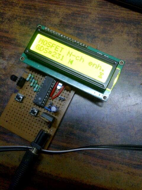
const unsigned char MOS_str[] PROGMEM = "MOS";
const unsigned char FET_str[] PROGMEM = "FET";
const unsigned char Channel_str[] PROGMEM = "-ch";
const unsigned char Enhancement_str[] PROGMEM = "enh.";
const unsigned char Depletion_str[] PROGMEM = "dep.";
const unsigned char IGBT_str[] PROGMEM = "IGBT";
const unsigned char GateCap_str[] PROGMEM = "Cgs=";
const unsigned char GDS_str[] PROGMEM = "GDS=";
const unsigned char GCE_str[] PROGMEM = "GCE=";
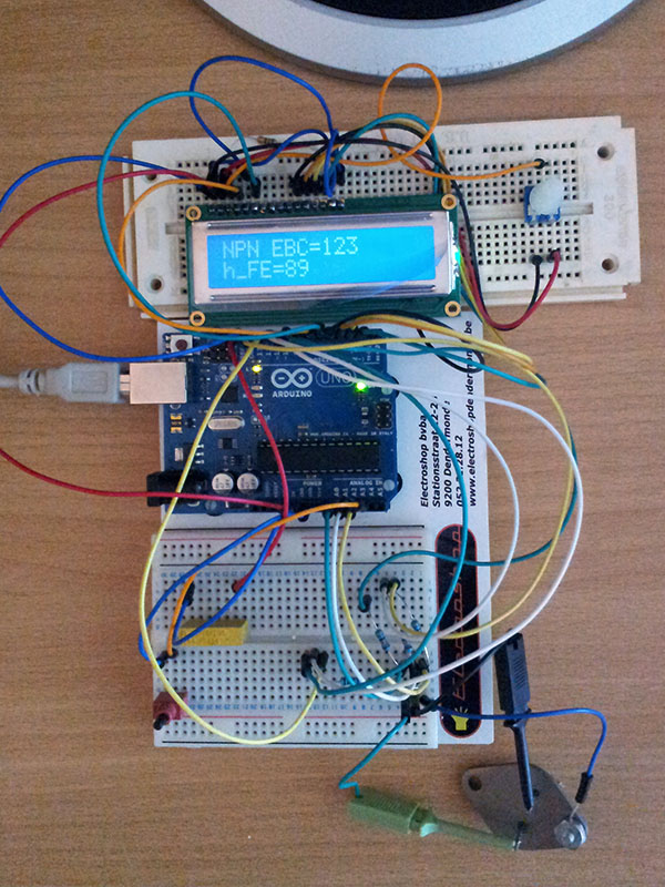
const unsigned char NPN_str[] PROGMEM = "NPN";
const unsigned char PNP_str[] PROGMEM = "PNP";
const unsigned char EBC_str[] PROGMEM = "EBC=";
const unsigned char hFE_str[] PROGMEM ="h_FE=";
const unsigned char V_BE_str[] PROGMEM ="V_BE=";
const unsigned char I_CEO_str[] PROGMEM = "I_CEO=";
const unsigned char Vf_str[] PROGMEM = "Vf=";
const unsigned char DiodeCap_str[] PROGMEM = "C=";
const unsigned char Vth_str[] PROGMEM = "Vth=";
const unsigned char I_R_str[] PROGMEM = "I_R=";
const unsigned char URef_str[] PROGMEM = "Vref";
const unsigned char RhLow_str[] PROGMEM = "Rh-";
const unsigned char RhHigh_str[] PROGMEM = "Rh+";
const unsigned char RiLow_str[] PROGMEM = "Ri-";
const unsigned char RiHigh_str[] PROGMEM = "Ri+";
const unsigned char Rl_str[] PROGMEM = "+Rl-";
const unsigned char Rh_str[] PROGMEM = "+Rh-";
const unsigned char ProbeComb_str[] PROGMEM = "12 13 23";
const unsigned char CapOffset_str[] PROGMEM = "C0";
const unsigned char ROffset_str[] PROGMEM = "R0";
const unsigned char CompOffset_str[] PROGMEM = "AComp";
const unsigned char PWM_str[] PROGMEM = "PWM";
const unsigned char Hertz_str[] PROGMEM = "Hz";
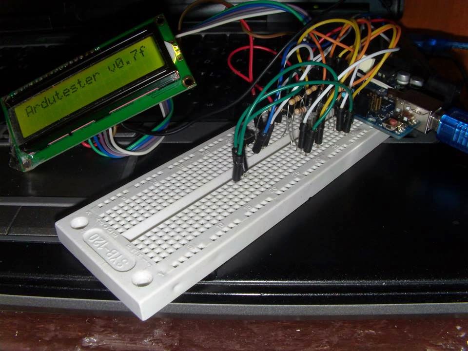
const unsigned char Splash_str[] PROGMEM = "Ardutester ";
const unsigned char Version_str[] PROGMEM = "v0.7f";
#ifdef DEBUG_PRINT
const unsigned char Cap_str[] PROGMEM = {'-','|','|', '-',0};
const unsigned char Diode_AC_str[] PROGMEM = {'-', '>', '-', 0};
const unsigned char Diode_CA_str[] PROGMEM = {'-', '<', '-', 0};
const unsigned char Diodes_str[] PROGMEM = {'*', '>', ' ', ' ', 0};
const unsigned char Resistor_str[] PROGMEM = {'-', '[', ']', '-', 0};
#else
const unsigned char Cap_str[] PROGMEM = {'-',LCD_CHAR_CAP, '-',0};
const unsigned char Diode_AC_str[] PROGMEM = {'-', LCD_CHAR_DIODE1, '-', 0};
const unsigned char Diode_CA_str[] PROGMEM = {'-', LCD_CHAR_DIODE2, '-', 0};
const unsigned char Diodes_str[] PROGMEM = {'*', LCD_CHAR_DIODE1, ' ', ' ', 0};
const unsigned char Resistor_str[] PROGMEM = {'-', LCD_CHAR_RESIS1, LCD_CHAR_RESIS2, '-', 0};
#endif
//Diode icon with anode at left side
byte DiodeIcon1[8] = {0x11, 0x19, 0x1d, 0x1f, 0x1d, 0x19, 0x11, 0x00};
//Diode icon with anode at right side
byte DiodeIcon2[8] = {0x11, 0x13, 0x17, 0x1f, 0x17, 0x13, 0x11, 0x00};
//Capacitor icon
byte CapIcon[8] = {0x1b, 0x1b, 0x1b, 0x1b, 0x1b, 0x1b, 0x1b, 0x00};
//Resistor icon #1 (left part)
byte ResIcon1[8] = {0x00, 0x0f, 0x08, 0x18, 0x08, 0x0f, 0x00, 0x00};
//Resistor icon #2 (right part)
byte ResIcon2[8] = {0x00, 0x1e, 0x02, 0x03, 0x02, 0x1e, 0x00, 0x00};
//Flag Icon
byte FlagIcon[8] = {0x1f, 0x11, 0x0e, 0x04, 0x0a, 0x15, 0x1f, 0x00};
//Prefix Table
const unsigned char Prefix_table[] = {'p', 'n', LCD_CHAR_MICRO, 'm', 0, 'k', 'M'};
//PWM menu: frequencies
const unsigned int PWM_Freq_table[] = {100, 250, 500, 1000, 2500, 5000, 10000, 25000};
//Voltage based factors for large caps (using Rl)
const unsigned int LargeCap_table[] = {23022, 21195, 19629, 18272, 17084, 16036, 15104, 14271, 13520, 12841, 12224, 11660, 11143, 10668, 10229, 9822, 9445, 9093, 8765, 8458, 8170, 7900, 7645, 7405, 7178, 6963, 6760, 6567, 6384, 6209, 6043, 5885, 5733, 5589, 5450, 5318, 5191, 5069, 4952, 4839, 4731, 4627, 4526, 4430, 4336};
//Voltage based factors for small caps (using Rh)
const unsigned int SmallCap_table[] = {954, 903, 856, 814, 775, 740, 707, 676, 648};
//Ratio based factors for inductors
const unsigned int Inductor_table[] = {4481, 3923, 3476, 3110, 2804, 2544, 2321, 2128, 1958, 1807, 1673, 1552, 1443, 1343, 1252, 1169, 1091, 1020, 953, 890, 831, 775, 721, 670, 621, 574, 527, 481, 434, 386, 334, 271};
//Bitmasks for Rl probe resistors based on probe ID
const unsigned char Rl_table[] = {(1 << (TP1 * 2)), (1 << (TP2 * 2)), (1 << (TP3 * 2))};
//Bitmasks for ADC pins based on probe ID
const unsigned char ADC_table[] = {(1 << TP1), (1 << TP2), (1 << TP3)};
//Function prototype
byte SmallCap(Capacitor_Type *Cap);
byte LargeCap(Capacitor_Type *Cap);
byte MeasureInductor(Resistor_Type *Resistor);
void ShowDiode_Uf(Diode_Type *Diode);
void ShowDiode_C(Diode_Type *Diode);
//Program control
byte RunsPassed; //Counter for successful measurements
byte RunsMissed; //Counter for failed/missed measurements
byte ErrFnd; //An Error is occured
//Setup function
void setup()
{
byte Test; //Test value
//Disable power on spi, twi, timer2
power_spi_disable();
power_twi_disable();
power_timer2_disable();
#ifdef LCD_PRINT
lcd.begin(16,2);
delay(5);
//Symbols for components
lcd.createChar(LCD_CHAR_DIODE1,DiodeIcon1); //Diode symbol |<|
lcd.createChar(LCD_CHAR_DIODE2,DiodeIcon2); //Diode symbol |<|
lcd.createChar(LCD_CHAR_CAP,CapIcon); //Capacitor symbol ||
lcd.createChar(LCD_CHAR_RESIS1,ResIcon1); //Resistor symbol [
lcd.createChar(LCD_CHAR_RESIS2,ResIcon2); //Resistor symbol ]
lcd.createChar(LCD_CHAR_FLAG,FlagIcon); //Flag symbol
lcd.home();
lcd_fixed_string(Splash_str);
lcd_fixed_string(Version_str);
#endif
#ifdef ATSW //Client Begin
Serial.begin(19200);
#endif
#ifdef DEBUG_PRINT
Serial.begin(9600); //Serial Output
#endif
//Setup Ă‚ÂľC
ADCSRA = (1 << ADEN) | ADC_CLOCK_DIV; //Enable ADC and set clock divider
MCUSR &= ~(1 << WDRF); //Reset watchdog flag
DIDR0 = 0b00110111;
wdt_disable(); //Disable watchdog
//Default offsets and values
Config.Samples = ADC_SAMPLES; //Number of ADC samples
Config.AutoScale = 1; //Enable ADC auto scaling
Config.RefFlag = 1; //No ADC reference set yet
delay(100);
//Reset variables
RunsMissed = 0;
RunsPassed = 0;
Config.TesterMode = MODE_CONTINOUS; //Set default mode: continous
#ifdef BUTTON_INST
pinMode(TEST_BUTTON, INPUT_PULLUP); //Initialize the pushbutton pin as an input
#endif
//Init
LoadAdjust(); //Load adjustment values
#ifdef DEBUG_PRINT
Serial.print(X("A R D U T E S T E R "));
lcd_fixed_string(Version_str); //Print Ardutester Version
Serial.println();
Serial.println(X(" By PighiXXX & PaoloP"));
Serial.println(X("original version by Markus Reschke"));
Serial.println();
#ifdef BUTTON_INST
Serial.print(X("Press Button to Probe"));
Serial.println(X(", long press enter Menu"));
#endif
#endif
delay(100);
}
//Main loop
void loop()
{
byte Test;
#ifdef BUTTON_INST
Test = TestKey(0, 0); //Wait user
#else
delay(3000); //No button installed, Wait 3 seconds
Test=1; //No button, no menu :-)
#endif
#ifdef WDT_enabled
wdt_enable(WDTO_2S); //Enable watchdog (timeout 2s)
#endif
//Reset variables
Check.Found = COMP_NONE;
Check.Type = 0;
Check.Done = 0;
Check.Diodes = 0;
Check.Resistors = 0;
BJT.hFE = 0;
BJT.I_CE0 = 0;
//Reset hardware
SetADCHiz(); //Set all pins of ADC port as input
lcd_clear(); //Clear LCD
#ifdef LCD_PRINT
lcd_fixed_string(Splash_str);
lcd_fixed_string(Version_str);
#endif
//Internal bandgap reference
Config.U_Bandgap = ReadU(0x0e); //Dummy read for bandgap stabilization
Config.Samples = 200; //Do a lot of samples for high accuracy
Config.U_Bandgap = ReadU(0x0e); //Get voltage of bandgap reference
Config.Samples = ADC_SAMPLES; //Set samples back to default
Config.U_Bandgap += Config.RefOffset; //Add voltage offset
if (Test==2) //Long Press
{
wdt_disable(); //Disable watchdog
MainMenu(); //Main Menu
}
else
{
if (AllProbesShorted() == 3) //All probes Shorted!
{
#ifdef DEBUG_PRINT
Serial.println();
#endif
lcd_fixed_string(Remove_str); //Display: Remove/Create
lcd_line(2);
lcd_fixed_string(ShortCircuit_str); //Display: short circuit!
}
else
{
//Display start of probing
lcd_line(2); //Move to line #2
lcd_fixed_string(Running_str); //Display: probing...
DischargeProbes();
if (Check.Found == COMP_ERROR) //Discharge failed
{ //Only for Standalone Version!
lcd_fixed_string(DischargeFailed_str); //Display: Battery?
//Display probe number and remaining voltage
lcd_line(2);
lcd_testpin(Check.Probe);
lcd_data(':');
lcd_space();
DisplayValue(Check.U, -3, 'V');
}
else //Skip all other checks
{
//Check all 6 combinations of the 3 probes
CheckProbes(TP1, TP2, TP3);
CheckProbes(TP2, TP1, TP3);
CheckProbes(TP1, TP3, TP2);
CheckProbes(TP3, TP1, TP2);
CheckProbes(TP2, TP3, TP1);
CheckProbes(TP3, TP2, TP1);
//If component might be a capacitor
if ((Check.Found == COMP_NONE) ||
(Check.Found == COMP_RESISTOR))
{
#ifdef DEBUG_PRINT
Serial.println();
Serial.println(X("Wait a moment..."));
#else
//Tell user to be patient with large caps
lcd_clear_line(2);
lcd_fixed_string(Running_str);
lcd_data('.');
#endif
//Check all possible combinations
MeasureCap(TP3, TP1, 0);
#ifdef LCD_PRINT
lcd_data('.');
#endif
MeasureCap(TP3, TP2, 1);
#ifdef LCD_PRINT
lcd_data('.');
#endif
MeasureCap(TP2, TP1, 2);
}
//Clear LCD
lcd_clear();
#ifdef BUTTON_INST
pinMode(TEST_BUTTON, INPUT_PULLUP); //Reinitialize the pushbutton pin as an input
#endif
//Call output function based on component type
#ifdef DEBUG_PRINT
Serial.print("Found: ");
//Components ID's
switch (Check.Found)
{
case COMP_ERROR:
Serial.println(X("Component Error!"));
break;
case COMP_NONE:
Serial.println(X("No Component!"));
break;
case COMP_RESISTOR:
Serial.println(X("Resistor"));
break;
case COMP_CAPACITOR:
Serial.println(X("Capacitor"));
break;
case COMP_INDUCTOR:
Serial.println(X("Inductor"));
break;
case COMP_DIODE:
Serial.println(X("Diode"));
break;
case COMP_BJT:
Serial.println(X("BJT"));
break;
case COMP_FET:
Serial.println(X("FET"));
break;
case COMP_IGBT:
Serial.println(X("IGBT"));
break;
case COMP_TRIAC:
Serial.println(X("TRIAC"));
break;
case COMP_THYRISTOR:
Serial.println(X("Thyristor"));
break;
}
#endif
switch (Check.Found)
{
case COMP_ERROR:
ShowError();
break;
case COMP_DIODE:
ShowDiode();
break;
case COMP_BJT:
ShowBJT();
break;
case COMP_FET:
ShowFET();
break;
case COMP_IGBT:
ShowIGBT();
break;
case COMP_THYRISTOR:
ShowSpecial();
break;
case COMP_TRIAC:
ShowSpecial();
break;
case COMP_RESISTOR:
ShowResistor();
break;
case COMP_CAPACITOR:
ShowCapacitor();
break;
default: //No component found
ShowFail();
}
#ifdef ATSW //Client output
Serial.println("@>");
Serial.println(Check.Found);
Serial.println("|");
Serial.println(Check.Type);
Serial.println("|");
Serial.println(Check.Done);
Serial.println("|");
Serial.println("@<");
//Component spedific output
#endif
//Component was found
RunsMissed = 0; //Reset counter
RunsPassed++; //Increase counter
}
}
}
delay(1000); //Let the user read the text
wdt_disable(); //Disable watchdog
}
//Set ADC port to HiZ mode
void SetADCHiz(void)
{
ADC_DDR &= ~(1<<TP1);
ADC_DDR &= ~(1<<TP2);
ADC_DDR &= ~(1<<TP3);
}
//Set ADC port low
void SetADCLow(void)
{
ADC_PORT &= ~(1<<TP1);
ADC_PORT &= ~(1<<TP2);
ADC_PORT &= ~(1<<TP3);
}
//Setup probes, bitmasks for probes and test resistors
void UpdateProbes(byte Probe1, byte Probe2, byte Probe3)
{
//DSt probe IDs
Probes.Pin_1 = Probe1;
Probes.Pin_2 = Probe2;
Probes.Pin_3 = Probe3;
//Setup masks using bitmask tables
Probes.Rl_1 = Rl_table[Probe1];
Probes.Rh_1 = Probes.Rl_1 + Probes.Rl_1;
Probes.ADC_1 = ADC_table[Probe1];
Probes.Rl_2 = Rl_table[Probe2];
Probes.Rh_2 = Probes.Rl_2 + Probes.Rl_2;
Probes.ADC_2 = ADC_table[Probe2];
Probes.Rl_3 = Rl_table[Probe3];
Probes.Rh_3 = Probes.Rl_3 + Probes.Rl_3;
}
//Check for a short circuit between two probes
byte ShortedProbes(byte Probe1, byte Probe2)
{
byte Flag = 0; //Return value
unsigned int U1; //Voltage at probe #1 in mV
unsigned int U2; //Voltage at probe #2 in mV
/*
Set up a voltage divider between the two probes:
- Probe1: Rl pull-up
- Probe2: Rl pull-down
- third probe: HiZ
*/
R_PORT = Rl_table[Probe1];
R_DDR = Rl_table[Probe1] | Rl_table[Probe2];
//Read voltages
U1 = ReadU(Probe1);
U2 = ReadU(Probe2);
/*
We expect both probe voltages to be about the same and
to be half of Vcc (allowed difference +/- 30mV).
*/
if ((U1 > UREF_VCC/2 - 30) && (U1 < UREF_VCC/2 + 30))
{
if ((U2 > UREF_VCC/2 - 30) && (U2 < UREF_VCC/2 + 30))
{
Flag = 1;
}
}
//Reset port
R_DDR = 0;
return Flag;
}
//Check for a short circuit between all probes
byte AllProbesShorted(void)
{
byte Flag = 0; //Return value
//Check all possible combinations
Flag = ShortedProbes(TP1, TP2);
Flag += ShortedProbes(TP1, TP3);
Flag += ShortedProbes(TP2, TP3);
return Flag;
}
//Try to discharge any connected components, e.g. capacitors
void DischargeProbes(void)
{
byte Counter; //Loop control
byte Limit = 40; //Sliding timeout (2s)
byte ID; //Test pin
byte DischargeMask; //Bitmask
unsigned int U_c; //Current voltage
unsigned int U_old[3]; //Old voltages
//Set probes to a save discharge mode (pull-down via Rh), Set ADC port to HiZ input
SetADCHiz();
SetADCLow();
//All probe pins: Rh and Rl pull-down
R_PORT = 0;
R_DDR = (2 << (TP1 * 2)) | (2 << (TP2 * 2)) | (2 << (TP3 * 2));
R_DDR |= (1 << (TP1 * 2)) | (1 << (TP2 * 2)) | (1 << (TP3 * 2));
//Get current voltages
U_old[0] = ReadU(TP1);
U_old[1] = ReadU(TP2);
U_old[2] = ReadU(TP3);
/*
Try to discharge probes
- We check if the voltage decreases over time.
- A slow discharge rate will increase the timeout to support
large caps.
- A very large cap will discharge too slowly and an external voltage
maybe never :-)
*/
Counter = 1;
ID = 2;
DischargeMask = 0;
while (Counter > 0)
{
ID++; //Next probe
if (ID > 2) ID = 0; //Start with probe #1 again
if (DischargeMask & (1 << ID)) //Skip discharged probe
continue;
U_c = ReadU(ID); //Get voltage of probe
if (U_c < U_old[ID]) //Voltage decreased
{
U_old[ID] = U_c; //Update old value
//Adapt timeout based on discharge rate
if ((Limit - Counter) < 20)
{
//Increase timeout while preventing overflow
if (Limit < (255 - 20)) Limit += 20;
}
Counter = 1; //Reset no-changes counter
}
else //Voltage not decreased
{
//Increase limit if we start at a low voltage
if ((U_c < 10) && (Limit <= 40)) Limit = 80;
Counter++; //Increase no-changes counter
}
if (U_c <= CAP_DISCHARGED) //Seems to be discharged
{
DischargeMask |= (1 << ID); //Set flag
}
else if (U_c < 800) //Extra pull-down
{
//It's save now to pull-down probe pin directly
ADC_DDR |= ADC_table[ID];
}
if (DischargeMask == 0b00000111) //All probes discharged
{
Counter = 0; //End loop
}
else if (Counter > Limit) //No decrease for some time
{
//Might be a battery or a super cap
Check.Found = COMP_ERROR; //Report error
Check.Type = TYPE_DISCHARGE; //Discharge problem
Check.Probe = ID; //Save probe
Check.U = U_c; //Save voltage
Counter = 0; //End loop
}
else //Go for another round
{
wdt_reset(); //Reset watchdog
delay(50); //Wait for 50ms
}
}
//Reset probes
R_DDR = 0; //Set resistor port to input mode
SetADCHiz(); //Set ADC port to input mode
}
//Pull probe up/down via probe resistor for 1 or 10 ms
void PullProbe(byte Mask, byte Mode)
{
//Set pull mode
if (Mode & FLAG_PULLUP) R_PORT |= Mask; //Pull-up
else R_PORT &= ~Mask; //Pull-down
R_DDR |= Mask; //Enable pulling
if (Mode & FLAG_1MS) delay(1); //Wait 1ms
else delay(10); //Wait 10ms
//Reset pulling
R_DDR &= ~Mask; //Set to HiZ mode
R_PORT &= ~Mask; //Set 0
}
//Rescale value
unsigned long RescaleValue(unsigned long Value, signed char Scale, signed char NewScale)
{
unsigned long NewValue;
NewValue = Value; //Take old value
while (Scale != NewScale) //Processing loop
{
if (NewScale > Scale) //Upscale
{
NewValue /= 10;
Scale++;
}
else //Downscale
{
NewValue *= 10;
Scale--;
}
}
return NewValue;
}
//Lokup a voltage/ratio based factor in a table and interpolate it's value
unsigned int GetFactor(unsigned int U_in, byte ID)
{
unsigned int Factor; //Return value
unsigned int U_Diff; //Voltage difference to table start
unsigned int Fact1, Fact2; //Table entries
unsigned int TabStart; //Table start voltage
unsigned int TabStep; //Table step voltage
unsigned int TabIndex; //Table entries (-2)
unsigned int *Table;
byte Index; //Table index
byte Diff; //Difference to next entry
//Setup table specific stuff
if (ID == TABLE_SMALL_CAP)
{
TabStart = 1000; //Table starts at 1000mV
TabStep = 50; //50mV steps between entries
TabIndex = 7; //Entries in table - 2
Table = (unsigned int *)&SmallCap_table[0]; //Pointer to table start
}
else if (ID == TABLE_LARGE_CAP)
{
TabStart = 300; //Table starts at 1000mV
TabStep = 25; //25mV steps between entries
TabIndex = 42; //Entries in table - 2
Table = (unsigned int *)&LargeCap_table[0]; //Pointer to table start
}
else if (ID == TABLE_INDUCTOR)
{
TabStart = 200; //Table starts at 200
TabStep = 25; //Steps between entries
TabIndex = 30; //Entries in table - 2
Table = (unsigned int *)&Inductor_table[0]; //Pointer to table start
}
else
{
return 0;
}
//We interpolate the table values corresponding to the given voltage/ratio, difference to start of table
if (U_in >= TabStart) U_Diff = U_in - TabStart;
else U_Diff = 0;
//Calculate table index
Index = U_Diff / TabStep; //Index (position in table)
Diff = U_Diff % TabStep; //Difference to index
Diff = TabStep - Diff; //Difference to next entry
//Prevent index overflow
if (Index > TabIndex) Index = TabIndex;
//Get values for index and next entry
Table += Index; //Advance to index
Fact1 = *(Table);
Table++; //Next entry
Fact2 = *(Table);
//Interpolate values based on the difference
Factor = Fact1 - Fact2;
Factor *= Diff;
Factor += TabStep / 2;
Factor /= TabStep;
Factor += Fact2;
return Factor;
}
//Identify component
void CheckProbes(byte Probe1, byte Probe2, byte Probe3)
{
byte Flag; //Temporary value
unsigned int U_Rl; //Voltage across Rl (load)
unsigned int U_1; //Voltage #1
//Init
if (Check.Found == COMP_ERROR) return; //Skip check on any error
wdt_reset(); //Reset watchdog
UpdateProbes(Probe1, Probe2, Probe3); //Update bitmasks
/*
We measure the current from probe 2 to ground with probe 1 pulled up
to 5V and probe 3 in HiZ mode to determine if we got a self-conducting
part, i.e. diode, resistor or depletion-mode FET. Rl is used as current
shunt.
In case of a FET we have to take care about the gate charge based on
the channel type.
*/
//Set probes: Gnd -- Rl -- probe-2 / probe-1 -- Vcc
R_PORT = 0; //Set resistor port to Gnd
R_DDR = Probes.Rl_2; //Pull down probe-2 via Rl
ADC_DDR = Probes.ADC_1; //Set probe-1 to output
ADC_PORT = Probes.ADC_1; //Pull-up probe-1 directly
/*
For a possible n channel FET we pull down the gate for a few ms,
assuming: probe-1 = D / probe-2 = S / probe-3 = G
*/
//Discharge gate via Rl
PullProbe(Probes.Rl_3, FLAG_10MS | FLAG_PULLDOWN);
U_Rl = ReadU_5ms(Probes.Pin_2); //Get voltage at Rl
/*
If we got conduction we could have a p channel FET. For any
other part U_Rl will be the same.
*/
if (U_Rl >= 977) // > 1.4mA
{
/*
For a possible p channel FET we pull up the gate for a few ms,
assuming: probe-1 = S / probe-2 = D / probe-3 = G
*/
//Discharge gate via Rl
PullProbe(Probes.Rl_3, FLAG_10MS | FLAG_PULLUP);
U_Rl = ReadU_5ms(Probes.Pin_2); //Get voltage at Rl
}
/*
If there's some current we could have a depletion-mode FET
(self-conducting). To skip germanium BJTs with a high leakage current
we check for a current larger then the usual V_CEO.
Other possibilities:
- diode or resistor
*/
if (U_Rl > 490) // > 700Ă‚ÂľA (was 92mV/130Ă‚ÂľA)
{
CheckDepletionModeFET(U_Rl);
}
/*
If there's nearly no conduction (just a small leakage current) between
probe-1 and probe-2 we might have a semiconductor:
- BJT
- enhancement mode FET
- Thyristor or Triac
or a large resistor
*/
if (U_Rl < 977) //Load current < 1.4mA
{
/*
check for:
- PNP BJT (common emitter circuit)
- p-channel MOSFET (low side switching circuit)
*/
if (Check.Done == 0) //Not sure yet
{
//We assume: probe-1 = E / probe-2 = C / probe-3 = B, set probes: Gnd -- Rl - probe-2 / probe-1 -- Vcc
R_DDR = Probes.Rl_2; //Enable Rl for probe-2
R_PORT = 0; //Pull down collector via Rl
ADC_DDR = Probes.ADC_1; //Set probe 1 to output
ADC_PORT = Probes.ADC_1; //Pull up emitter directly
delay(5);
R_DDR = Probes.Rl_2 | Probes.Rl_3; //Pull down base via Rl
U_1 = ReadU_5ms(Probe2); //Get voltage at collector
//If DUT is conducting we might have a PNP BJT or p-channel FET.
if (U_1 > 3422) //Detected current > 4.8mA
{
//Distinguish PNP BJT from p-channel MOSFET
CheckBJTorEnhModeMOSFET(TYPE_PNP, U_Rl);
}
}
/*
Check for
- NPN BJT (common emitter circuit)
- Thyristor and Triac
- n-channel MOSFET (high side switching circuit)
*/
if (Check.Done == 0) //Not sure yet
{
//We assume: probe-1 = C / probe-2 = E / probe-3 = B, set probes: Gnd -- probe-2 / probe-1 -- Rl -- Vcc
ADC_DDR = Probes.ADC_2; //Set probe-2 to output mode
SetADCLow(); //Pull down probe-2 directly
R_DDR = Probes.Rl_1 | Probes.Rl_3; //Select Rl for probe-1 & Rl for probe-3
R_PORT = Probes.Rl_1 | Probes.Rl_3; //Pull up collector & base via Rl
U_1 = ReadU_5ms(Probe1); //Get voltage at collector
//If DUT is conducting we might have a NPN BJT, something similar or a n-channel MOSFET.
if (U_1 < 1600) //Detected current > 4.8mA
{
//First check for thyristor and triac
Flag = CheckThyristorTriac();
if (Flag == 0) //No thyristor or triac
{
//We might got a NPN BJT or a n-channel MOSFET.
CheckBJTorEnhModeMOSFET(TYPE_NPN, U_Rl);
}
}
}
}
/*
If there's conduction between probe-1 and probe-2 we might have a
- diode (conducting)
- small resistor (checked later on)
*/
else //Load current > 1.4mA
{
//We check for a diode even if we already found a component to get Vf, since there could be a body/protection diode of a transistor.
CheckDiode();
}
//Check for a resistor.
if ((Check.Found == COMP_NONE) ||
(Check.Found == COMP_RESISTOR))
{
CheckResistor();
}
//Otherwise run some final checks.
else
{
//Verify a MOSFET
if ((Check.Found == COMP_FET) && (Check.Type & TYPE_MOSFET))
VerifyMOSFET();
}
//Clean up
SetADCHiz(); //Set ADC port to HiZ mode
SetADCLow(); //Set ADC port low
R_DDR = 0; //Set resistor port to HiZ mode
R_PORT = 0; //Set resistor port low
}
//Read ADC and return voltage in mV
unsigned int ReadU(byte Probe)
{
unsigned int U; //Return value (mV)
byte Counter; //Loop counter
unsigned long Value; //ADC value
boolean cycle;
Probe |= (1 << REFS0); //Use internal reference anyway
do {
cycle = false;
ADMUX = Probe; //Set input channel and U reference
//If voltage reference has changed run a dummy conversion (recommended by datasheet)
Counter = Probe & (1 << REFS1); //Get REFS1 bit flag
if (Counter != Config.RefFlag)
{
waitus(100); //Time for voltage stabilization
ADCSRA |= (1 << ADSC); //Start conversion
while (ADCSRA & (1 << ADSC)); //Wait until conversion is done
Config.RefFlag = Counter; //Update flag
}
//Sample ADC readings
Value = 0UL; //Reset sampling variable
Counter = 0; //Reset counter
while (Counter < Config.Samples) //Take samples
{
ADCSRA |= (1 << ADSC); //Start conversion
while (ADCSRA & (1 << ADSC)); //Wait until conversion is done
Value += ADCW; //Add ADC reading
//Auto-switch voltage reference for low readings
if (Counter == 4)
{
if (((unsigned int)Value < 1024) && !(Probe & (1 << REFS1)) && (Config.AutoScale == 1))
{
Probe |= (1 << REFS1); //Select internal bandgap reference
cycle = true; //Re-run sampling
break;
}
}
Counter++; //One less to do
}
} while (cycle);
//Convert ADC reading to voltage - single sample: U = ADC reading * U_ref / 1024
//Get voltage of reference used
if (Probe & (1 << REFS1)) U = Config.U_Bandgap;//Bandgap reference
else U = UREF_VCC; //Vcc reference
//Convert to voltage;
Value *= U; //ADC readings * U_ref
Value /= 1024; // / 1024 for 10bit ADC
//De-sample to get average voltage
Value /= Config.Samples;
U = (unsigned int)Value;
return U;
}
//Wait 5ms and then read ADC
unsigned int ReadU_5ms(byte Probe)
{
delay(5); //Wait 5ms
return (ReadU(Probe));
}
//Wait 20ms and then read ADC
unsigned int ReadU_20ms(byte Probe)
{
delay(20); //Wait 20ms
return (ReadU(Probe));
}
//Wait Functions
void waitus(byte microsec) {
delayMicroseconds(microsec);
}
//Measure hFE of BJT in common collector circuit (emitter follower)
unsigned long Get_hFE_C(byte Type)
{
unsigned long hFE; //Return value
unsigned int U_R_e; //Voltage across emitter resistor
unsigned int U_R_b; //Voltage across base resistor
unsigned int Ri; //Internal resistance of Ă‚ÂľC
/*
Measure hFE for a BJT in common collector circuit
(emitter follower):
- hFE = (I_e - I_b) / I_b
- measure the voltages across the resistors and calculate the currents
(resistor values are well known)
- hFE = ((U_R_e / R_e) - (U_R_b / R_b)) / (U_R_b / R_b)
*/
//Setup probes and get voltages
if (Type == TYPE_NPN) //NPN
{
//We assume: probe-1 = C / probe-2 = E / probe-3 = B, set probes: Gnd -- Rl -- probe-2 / probe-1 -- Vcc
ADC_DDR = Probes.ADC_1; //Set probe 1 to output
ADC_PORT = Probes.ADC_1; //Pull up collector directly
R_DDR = Probes.Rl_2 | Probes.Rl_3; //Select Rl for probe-2 & Rl for probe-3
R_PORT = Probes.Rl_3; //Pull up base via Rl
U_R_e = ReadU_5ms(Probes.Pin_2); //U_R_e = U_e
U_R_b = UREF_VCC - ReadU(Probes.Pin_3); //U_R_b = Vcc - U_b
}
else //PNP
{
//We assume: probe-1 = E / probe-2 = C / probe-3 = B, set probes: Gnd -- probe-2 / probe-1 -- Rl -- Vcc
SetADCLow(); //Set ADC port low
ADC_DDR = Probes.ADC_2; //Pull down collector directly
R_PORT = Probes.Rl_1; //Pull up emitter via Rl
R_DDR = Probes.Rl_1 | Probes.Rl_3; //Pull down base via Rl
U_R_e = UREF_VCC - ReadU_5ms(Probes.Pin_1); //U_R_e = Vcc - U_e
U_R_b = ReadU(Probes.Pin_3); //U_R_b = U_b
}
if (U_R_b < 10) //I_b < 14Ă‚ÂľA -> Darlington
{
//Change base resistor from Rl to Rh and measure again
if (Type == TYPE_NPN) //NPN
{
R_DDR = Probes.Rl_2 | Probes.Rh_3; //Select Rl for probe-2 & Rh for probe-3
R_PORT = Probes.Rh_3; //Pull up base via Rh
U_R_e = ReadU_5ms(Probes.Pin_2); //U_R_e = U_e
U_R_b = UREF_VCC - ReadU(Probes.Pin_3); //U_R_b = Vcc - U_b
Ri = Config.RiL; //Get internal resistor
}
else //PNP
{
R_DDR = Probes.Rl_1 | Probes.Rh_3; //Pull down base via Rh
U_R_e = UREF_VCC - ReadU_5ms(Probes.Pin_1);//U_R_e = Vcc - U_e
U_R_b = ReadU(Probes.Pin_3); //U_R_b = U_b
Ri = Config.RiH; //Get internal resistor
}
/*
Since I_b is so small vs. I_e we'll neglect it and use
hFE = I_e / I_b
= (U_R_e / R_e) / (U_R_b / R_b)
= (U_R_e * R_b) / (U_R_b * R_e)
*/
if (U_R_b < 1) U_R_b = 1; //Prevent division by zero
hFE = U_R_e * R_HIGH; //U_R_e * R_b
hFE /= U_R_b; // / U_R_b
hFE *= 10; //Upscale to 0.1
hFE /= (R_LOW * 10) + Ri; // / R_e in 0.1 Ohm
}
else //I_b > 14Ă‚ÂľA -> standard
{
/*
Both resistors are the same (R_e = R_b):
- hFE = ((U_R_e / R_e) - (U_R_b / R_b)) / (U_R_b / R_b)
- = (U_R_e - U_R_b) / U_R_b
*/
hFE = (unsigned long)((U_R_e - U_R_b) / U_R_b);
}
return hFE;
}
//Measure the gate threshold voltage of a depletion-mode MOSFET
void GetGateThreshold(byte Type)
{
unsigned long Uth = 0; //Gate threshold voltage
byte Drain_Rl; //Rl bitmask for drain
byte Drain_ADC; //ADC bitmask for drain
byte PullMode;
byte Counter; //Loop counter
//Init variables
if (Type & TYPE_N_CHANNEL) //n-channel
{
/*
We assume: probe-1 = D / probe-2 = S / probe-3 = G
probe-2 is still pulled down directly
probe-1 is still pulled up via Rl
*/
Drain_Rl = Probes.Rl_1;
Drain_ADC = Probes.ADC_1;
PullMode = FLAG_10MS | FLAG_PULLDOWN;
}
else //p-channel
{
/*
We assume: probe-1 = S / probe-2 = D / probe-3 = G
probe-2 is still pulled down via Rl
probe-1 is still pulled up directly
*/
Drain_Rl = Probes.Rl_2;
Drain_ADC = Probes.ADC_2;
PullMode = FLAG_10MS | FLAG_PULLUP;
}
//For low reaction times we use the ADC directly.
//Sanitize bit mask for drain to prevent a never-ending loop
Drain_ADC &= 0b00000111; //drain
ADMUX = Probes.Pin_3 | (1 << REFS0); //Select probe-3 for ADC input
//Sample 10 times
for (Counter = 0; Counter < 10; Counter++)
{
wdt_reset(); //Reset watchdog
//Discharge gate via Rl for 10 ms
PullProbe(Probes.Rl_3, PullMode);
//Pull up/down gate via Rh to slowly charge gate
R_DDR = Drain_Rl | Probes.Rh_3;
//Wait until FET conducts
if (Type & TYPE_N_CHANNEL) //n-channel
{
//FET conducts when the voltage at drain reaches low level
while (ADC_PIN & Drain_ADC);
}
else //p-channel
{
//FET conducts when the voltage at drain reaches high level
while (!(ADC_PIN & Drain_ADC));
}
R_DDR = Drain_Rl; //Set probe-3 to HiZ mode
//Get voltage of gate
ADCSRA |= (1 << ADSC); //Start ADC conversion
while (ADCSRA & (1 << ADSC)); //Wait until conversion is done
//Add ADC reading
if (Type & TYPE_N_CHANNEL) //n-channel
{
Uth += ADCW; //U_g = U_measued
}
else //p-channel
{
Uth += (1023 - ADCW); //U_g = Vcc - U_measured
}
}
//Calculate V_th
Uth /= 10; //Average of 10 samples
Uth *= UREF_VCC; //Convert to voltage
Uth /= 1024; //Using 10 bit resolution
//Save data
FET.V_th = (unsigned int)Uth;
}
//Measure leakage current
unsigned int GetLeakageCurrent(void)
{
unsigned int I_leak = 0; //Return value
unsigned int U_Rl; //Voltage at Rl
unsigned int R_Shunt; //Shunt resistor
uint32_t Value;
/*
Setup probes:
- use Rl as current shunt
- probe-1 = pos / probe-2 = neg / probe-3 = HiZ
Diode: probe-1 = cathode / probe-2 = anode
NPN BJT: probe-1 = collector / probe-2 = emitter
PNP BJT: probe-1 = emitter / probe-2 = collector
*/
R_PORT = 0; //Set resistor port to Gnd
R_DDR = Probes.Rl_2; //Pull down probe-2 via Rl
ADC_DDR = Probes.ADC_1; //Set probe-1 to output
ADC_PORT = Probes.ADC_1; //Pull-up probe-1 directly
U_Rl = ReadU_5ms(Probes.Pin_2); //Get voltage at Rl
//Calculate current
R_Shunt = Config.RiL + (R_LOW * 10); //Consider internal resistance of MCU (0.1 Ohms)
R_Shunt += 5; //For rounding
R_Shunt /= 10; //Scale to Ohms
Value = U_Rl * 100000; //Scale to 10nV
Value /= R_Shunt; //in 10nA
Value += 55; //For rounding
Value /= 100; //Scale to Ă‚ÂľA
I_leak = Value;
//Clean up
SetADCHiz(); //Set ADC port to HiZ mode
SetADCLow(); //Set ADC port low
R_DDR = 0; //Set resistor port to HiZ mode
R_PORT = 0; //Set resistor port low
return I_leak;
}
//Check for diode
void CheckDiode(void)
{
Diode_Type *Diode; //Pointer to diode
unsigned int U1_Rl; //Vf #1 with Rl pull-up
unsigned int U1_Rh; //Vf #1 with Rh pull-up
unsigned int U1_Zero; //Vf #1 zero
unsigned int U2_Rl; //Vf #2 with Rl pull-up
unsigned int U2_Rh; //Vf #2 with Rh pull-up
unsigned int U2_Zero; //Vf #2 zero
wdt_reset(); //Reset watchdog
DischargeProbes(); //Try to discharge probes
if (Check.Found == COMP_ERROR) return; //Skip on error
/*
DUT could be:
- simple diode
- protection diode of a MOSFET or another device
- intrinsic diode junction of a BJT
- small resistor (< 3k)
- capacitor (> around 22Ă‚ÂľF)
Solution:
- Vf of a diode rises with the current within some limits (about twice
for Si and Schottky). Ge, Z-diodes and LEDs are hard to determine.
So it might be better to filter out other components.
- For a MOSFET pretection diode we have to make sure that the MOSFET
in not conducting, to be able to get Vf of the protection diode.
So we discharge the gate and run the measurements twice for p and n
channel FETs.
- Take care about the internal voltage drop of the Ă‚ÂľC at the cathode
for high test currents (Rl).
- Filter out resistors by the used voltage divider:
k = Rl + Ri_H + Ri_L
U_Rh = U_Rl / (k - (k - 1) U_Rl / 5V)
U_Rl = k U_Rh / (1 + (k - 1) U_Rh / 5V)
- Filter out caps by checking the voltage before and after measurement
with Rh. In 15ms a 22Ă‚ÂľF cap would be charged from 0 to 7mV, a larger
cap would have a lower voltage. We have to consider that caps also
might be charged by EMI.
Hints:
- Rl drives a current of about 7mA. That's not the best current for
measuring Vf. The current for Rh is about 10.6Ă‚ÂľA.
Most DMMs use 1mA.
Vf #1, supporting a possible p-channel MOSFET
*/
//We assume: probe-1 = A / probe2 = C, set probes: Gnd -- probe-2 / probe-1 -- Rl or Rh -- Vcc
SetADCLow();
ADC_DDR = Probes.ADC_2; //Pull down cathode directly
//R_DDR is set to HiZ by DischargeProbes();
U1_Zero = ReadU(Probes.Pin_1); //Get voltage at anode
//Measure voltage across DUT (Vf) with Rh
R_DDR = Probes.Rh_1; //Enable Rh for probe-1
R_PORT = Probes.Rh_1; //Pull up anode via Rh
//Discharge gate
PullProbe(Probes.Rl_3, FLAG_10MS | FLAG_PULLUP);
U1_Rh = ReadU_5ms(Probes.Pin_1); //Get voltage at anode, neglect voltage at cathode
//Measure voltage across DUT (Vf) with Rl
R_DDR = Probes.Rl_1; //Enable Rl for probe-1
R_PORT = Probes.Rl_1; //Pull up anode via Rl
//Discharge gate
PullProbe(Probes.Rl_3, FLAG_10MS | FLAG_PULLUP);
U1_Rl = ReadU_5ms(Probes.Pin_1); //Get voltage at anode
U1_Rl -= ReadU(Probes.Pin_2); //Substract voltage at cathode
DischargeProbes(); //Try to discharge probes
if (Check.Found == COMP_ERROR) return; //Skip on error
//Vf #2, supporting a possible n-channel MOSFET
//We assume: probe-1 = A / probe2 = C, set probes: Gnd -- probe-2 / probe-1 -- Rl or Rh -- Vcc
SetADCLow();
ADC_DDR = Probes.ADC_2; //Pull down cathode directly
U2_Zero = ReadU(Probes.Pin_1); //Get voltage at anode
//Measure voltage across DUT (Vf) with Rh
R_DDR = Probes.Rh_1; //Enable Rh for probe-1
R_PORT = Probes.Rh_1; //Pull up anode via Rh
//Discharge gate
PullProbe(Probes.Rl_3, FLAG_10MS | FLAG_PULLDOWN);
U2_Rh = ReadU_5ms(Probes.Pin_1); //Get voltage at anode, neglect voltage at cathode
//Measure voltage across DUT (Vf) with Rl
R_DDR = Probes.Rl_1; //Enable Rl for probe-1
R_PORT = Probes.Rl_1; //Pull up anode via Rl
//Discharge gate
PullProbe(Probes.Rl_3, FLAG_10MS | FLAG_PULLDOWN);
U2_Rl = ReadU_5ms(Probes.Pin_1); //Get voltage at anode
U2_Rl -= ReadU(Probes.Pin_2); //Substract voltage at cathode
R_PORT = 0; //Stop pulling up
//Process results, choose between measurements of p and n channel setup
if (U1_Rl > U2_Rl) //The higher voltage wins
{
U2_Rl = U1_Rl;
U2_Rh = U1_Rh;
U2_Zero = U1_Zero;
}
/*
U_Rh < 10mV for
- resistor < 1k Ohm
- very large cap
*/
if (U2_Rh <= 10) return; //Small resistor or very large cap
/*
U_Zero <= 2 for resistor or diode
U_Zero > 2 for cap or diode
if U_Zero > 2 then U_Rh - U_Zero < 100 for cap
Hints:
If U_Zero > 10 and U_Rh is about U_Zero it's a large cap.
As larger the cap as lower U_Rl (charging time 15ms).
*/
U1_Zero = U2_Rh - U2_Zero; //Voltage difference
if ((U2_Zero > 2) && (U1_Zero < 100)) return; //Capacitor
/*
The voltages for a resistor will follow the equation:
k = Rl + Ri_H + Ri_L
Ul = k U_Rh / (1 + (k - 1) U_Rh / 5V)
Allow a tolerance of 3%.
For U_Rh > 40mV we don't need to check for a resistor.
Hint:
Actually we could change the thresshold above from 10 t0 40 and
remove this test completely. The lowest U_Rh measured for a diode was
56mV for a AA118.
*/
if (U2_Rh < 40) //Resistor (< 3k)
{
uint32_t a, b;
//Calculate expected U_Rl based on measured U_Rh in mV, k factor
b = (R_HIGH * 10) / ((R_LOW * 10) + Config.RiH + Config.RiL);
a = b - 1; //k - 1
a /= 5; // / 5V
a *= U2_Rh; // *U_Rh
a += 1000; // +1 (1000 for mV)
b *= 1000; //For mV
b *= U2_Rh; // *U_Rh
b /= a; //U_Rl in mV
//Check if calculated U_Rl is within some % of measured value
U1_Zero = (unsigned int)b;
U1_Rl = U1_Zero;
U1_Rh = U1_Zero;
U1_Zero /= 50; //2%
U1_Rh += U1_Zero; //102%
U1_Zero = (unsigned int)b;
U1_Zero /= 33; //3%
U1_Rl -= U1_Zero; //97% (for resistors near 1k)
//Resistor
if ((U2_Rl >= U1_Rl) && (U2_Rl <= U1_Rh)) return;
}
//If U_Rl (Vf) is between 0.15V and 4.64V it's a diode
if ((U2_Rl > 150) && (U2_Rl < 4640))
{
//If we haven't found any other component yet
if ((Check.Found == COMP_NONE) ||
(Check.Found == COMP_RESISTOR))
{
Check.Found = COMP_DIODE;
}
//Save data
Diode = &Diodes[Check.Diodes];
Diode->A = Probes.Pin_1;
Diode->C = Probes.Pin_2;
Diode->V_f = U2_Rl; //Vf for high measurement current
Diode->V_f2 = U2_Rh; //Vf for low measurement current
Check.Diodes++;
}
}
//Verify MOSFET by checking the body diode
void VerifyMOSFET(void)
{
byte Flag = 0;
byte n = 0;
byte Anode;
byte Cathode;
Diode_Type *Diode; //Pointer to diode
//Set expected body diode
if (Check.Type & TYPE_N_CHANNEL) //n-channel
{
Anode = FET.S;
Cathode = FET.D;
}
else //p-channel
{
Anode = FET.D;
Cathode = FET.S;
}
Diode = &Diodes[0]; //First diode
//Check all known diodes for reversed one
while (n < Check.Diodes)
{
if ((Diode->A == Cathode) && (Diode->C == Anode))
{
Flag = 1; //Signal match
n = 10; //End loop
}
n++; //Next diode
Diode++;
}
if (Flag == 1) //Found reversed diode
{
//This can't be a MOSFET, so let's reset
Check.Found = COMP_NONE;
Check.Type = 0;
Check.Done = 0;
}
}
//Check for BJT or enhancement-mode MOSFET
void CheckBJTorEnhModeMOSFET(byte BJT_Type, unsigned int U_Rl)
{
byte FET_Type; //MOSFET type
unsigned int U_R_c; //Voltage across collector resistor
unsigned int U_R_b; //Voltage across base resistor
unsigned int BJT_Level; //Voltage threshold for BJT
unsigned int FET_Level; //Voltage threshold for FET
unsigned int I_CE0; //Leakage current
unsigned long hFE_C; //hFE (common collector)
unsigned long hFE_E; //hFE (common emitter)
//Init, set probes and measure
if (BJT_Type == TYPE_NPN) //NPN / n-channel
{
BJT_Level = 2557; //Voltage across base resistor (5.44Ă‚ÂľA)
FET_Level = 3400; //Voltage across drain resistor (4.8mA)
FET_Type = TYPE_N_CHANNEL;
/*
We assume
- BJT: probe-1 = C / probe-2 = E / probe-3 = B
- FET: probe-1 = D / probe-2 = S / probe-3 = G
probes already set to: Gnd -- probe-2 / probe-1 -- Rl -- Vcc
drive base/gate via Rh instead of Rl
*/
R_DDR = Probes.Rl_1 | Probes.Rh_3; //Enable Rl for probe-1 & Rh for probe-3
R_PORT = Probes.Rl_1 | Probes.Rh_3; //Pull up collector via Rl and base via Rh
delay(50); //Wait to skip gate charging of a FET
U_R_c = UREF_VCC - ReadU(Probes.Pin_1); //U_R_c = Vcc - U_c
U_R_b = UREF_VCC - ReadU(Probes.Pin_3); //U_R_b = Vcc - U_b
}
else //PNP / p-channel
{
BJT_Level = 977; //Voltage across base resistor (2.1Ă‚ÂľA)
FET_Level = 2000; //Voltage across drain resistor (2.8mA)
FET_Type = TYPE_P_CHANNEL;
/*
We assume
- BJT: probe-1 = E / probe-2 = C / probe-3 = B
- FET: probe-1 = S / probe-2 = D / probe-3 = G
probes already set to: Gnd -- Rl - probe-2 / probe-1 -- Vcc
drive base/gate via Rh instead of Rl
*/
R_DDR = Probes.Rl_2 | Probes.Rh_3; //Pull down base via Rh
U_R_c = ReadU_5ms(Probes.Pin_2); //U_R_c = U_c
U_R_b = ReadU(Probes.Pin_3); //U_R_b = U_b
}
//Distinguish BJT from depletion-mode MOSFET
if (U_R_b > BJT_Level) //U_R_b exceeds minimum level of BJT
{
/*
A voltage drop across the base resistor Rh means that a current
is flowing constantly. So this can't be a FET.
Problem:
A reversed collector and emitter also passes the tests, but with
a low hFE. So we need to run two tests to be sure and select the
test results with the higher hFE.
*/
//Two test runs needed at maximium to get right hFE & pins
if (Check.Found == COMP_BJT) Check.Done = 1;
Check.Found = COMP_BJT;
Check.Type = BJT_Type;
//Leakage current
I_CE0 = GetLeakageCurrent(); //Get leakage current (in Ă‚ÂľA)
/*
Calculate hFE via voltages and known resistors:
- hFE = I_c / I_b
= (U_R_c / R_c) / (U_R_b / R_b)
= (U_R_c * R_b) / (U_R_b * R_c)
- consider leakage current:
I_c = I_c_conducting - I_c_leak
= (U_R_c_conducting / R_c) - (U_R_c_leak / R_c)
= (U_R_c_conducting - U_R_c_leak) / R_c
-> U_R_c = U_R_c_conducting - U_R_c_leak
= U_R_c_conducting - U_Rl
*/
if (U_R_c > U_Rl) U_R_c -= U_Rl; // - U_Rl (leakage)
hFE_E = U_R_c * R_HIGH; //U_R_c * R_b
hFE_E /= U_R_b; // / U_R_b
hFE_E *= 10; //Upscale to 0.1
if (BJT_Type == TYPE_NPN) //NPN
hFE_E /= (R_LOW * 10) + Config.RiH; // / R_c in 0.1 Ohm
else //PNP
hFE_E /= (R_LOW * 10) + Config.RiL; // / R_c in 0.1 Ohm
//Get hFE for common collector circuit
hFE_C = Get_hFE_C(BJT_Type);
//Keep largest hFE
if (hFE_C > hFE_E) hFE_E = hFE_C;
//Only update data if hFE is larger than old one
if (hFE_E > BJT.hFE)
{
//Save data
BJT.hFE = hFE_E;
BJT.I_CE0 = I_CE0;
BJT.B = Probes.Pin_3;
if (BJT_Type == TYPE_NPN) //NPN
{
BJT.C = Probes.Pin_1;
BJT.E = Probes.Pin_2;
}
else //PNP
{
BJT.C = Probes.Pin_2;
BJT.E = Probes.Pin_1;
}
}
#if 0
/*
Check for proper emitter and collector:
- I_c is much lower for reversed emitter and collector.
- So we reverse the probes and measure I_c (= U_R_c / R_c) again.
- Since R_c is constant we may simply compare U_R_c.
This is an alternative solution instead of running the check two times.
*/
SetADCHiz(); //Set ADC port to HiZ mode
R_DDR = 0; //Set resistor port to HiZ mode
if (BJT_Type == TYPE_NPN) //NPN
{
//We assume: probe-1 = E / probe-2 = C / probe-3 = B, set probes: Gnd -- probe-1 / probe-2 -- Rl -- Vcc
SetADCLow();
ADC_DDR = Probes.ADC_1; //Pull-down emitter directly
R_PORT = Probes.Rl_2 | Probes.Rh_3; //Pull-up base via Rh
R_DDR = Probes.Rl_2 | Probes.Rh_3; //Enable probe resistors
U_R_b = UREF_VCC - ReadU_5ms(Probes.Pin_2);//U_R_c = Vcc - U_c
}
else //PNP
{
//We assume: probe-1 = C / probe-2 = E / probe-3 = B, set probes: Gnd -- Rl - probe-1 / probe-2 -- Vcc
R_PORT = 0;
R_DDR = Probes.Rl_1 | Probes.Rh_3; //Pull down base via Rh
ADC_DDR = Probes.ADC_2;
ADC_PORT = Probes.ADC_2; //Pull-up emitter directly
U_R_b = ReadU_5ms(Probes.Pin_1); //U_R_c = U_c
}
//If not reversed, BJT is identified
if (U_R_c > U_R_b) //I_c > I_c_reversed
{
//Move other stuff here: save data & Comp=
Check.Done = 1;
}
#endif
}
else if ((U_Rl < 97) && (U_R_c > FET_Level)) //No BJT
{
/*
If there's
- just a small leakage current (< 0.1mA) in non-conducting mode
- a large U_R_c (= large current) when conducting
- a low U_R_b (= very low gate current)
we got a FET or an IGBT.
The drain source channel of a MOSFET is modeled as a resistor
while an IGBT acts more like a diode. So we measure the voltage drop
across the conducting path. A MOSFET got a low voltage drop based on
it's R_DS_on and the current. An IGBT got a much higher voltage drop.
*/
I_CE0= ReadU(Probes.Pin_1) - ReadU(Probes.Pin_2);
if (I_CE0 < 250) //MOSFET
{
Check.Found = COMP_FET;
Check.Type = FET_Type | TYPE_ENHANCEMENT | TYPE_MOSFET;
}
else //IGBT
{
Check.Found = COMP_IGBT;
Check.Type = FET_Type | TYPE_ENHANCEMENT;
}
Check.Done = 1; //Transistor found
//Measure gate threshold voltage
GetGateThreshold(FET_Type);
//Save data
FET.G = Probes.Pin_3;
if (FET_Type == TYPE_N_CHANNEL) //n-channel
{
FET.D = Probes.Pin_1;
FET.S = Probes.Pin_2;
}
else //p-channel
{
FET.D = Probes.Pin_2;
FET.S = Probes.Pin_1;
}
}
}
//Check for a depletion mode FET (self conducting)
void CheckDepletionModeFET(unsigned int U_Rl_L)
{
unsigned int U_1; //Voltage #1
unsigned int U_2; //Voltage #2
/*
Required probe setup (by calling function):
- Gnd -- Rl -- probe-2 / probe-1 -- Vcc
Check if we got a n-channel JFET or depletion-mode MOSFET
- JFETs are depletion-mode only
*/
if (Check.Done == 0) //No transistor found yet
{
//We assume: probe-1 = D / probe-2 = S / probe-3 = G, probes already set to: Gnd -- Rl -- probe-2 / probe-1 -- Vcc
R_DDR = Probes.Rl_2 | Probes.Rh_3; //Pull down gate via Rh
U_1 = ReadU_20ms(Probes.Pin_2); //Voltage at source
R_PORT = Probes.Rh_3; //Pull up gate via Rh
U_2 = ReadU_20ms(Probes.Pin_2); //Voltage at source
/*
If the source voltage is higher when the gate is driven by a positive
voltage vs. connected to ground we got a depletion-mode n-channel FET.
The source resistor creates a voltage offset based on the current
causing V_GS to become negative with the gate pulled down.
*/
if (U_2 > (U_1 + 488))
{
//Compare gate voltages to distinguish JFET from MOSFET
//Set probes: Gnd -- probe-2 / probe-1 -- Rl -- Vcc
SetADCLow(); //Set ADC port to low
ADC_DDR = Probes.ADC_2; //Pull down source directly
R_DDR = Probes.Rl_1 | Probes.Rh_3; //Enable Rl for probe-1 & Rh for probe-3
R_PORT = Probes.Rl_1 | Probes.Rh_3; //Pull up drain via Rl / pull up gate via Rh
U_2 = ReadU_20ms(Probes.Pin_3); //Get voltage at gate
if (U_2 > 3911) //MOSFET
{
//n channel depletion-mode MOSFET
Check.Type = TYPE_N_CHANNEL | TYPE_DEPLETION | TYPE_MOSFET;
}
else //JFET
{
//n channel JFET (depletion-mode only)
Check.Type = TYPE_N_CHANNEL | TYPE_JFET;
}
//Save data
Check.Found = COMP_FET;
Check.Done = 1;
FET.G = Probes.Pin_3;
FET.D = Probes.Pin_1;
FET.S = Probes.Pin_2;
}
}
//Check if we got a p-channel JFET or depletion-mode MOSFET - JFETs are depletion-mode only
if (Check.Done == 0) //No transistor found yet
{
//We assume: probe-1 = S / probe-2 = D / probe-3 = G, set probes: Gnd -- probe-2 / probe-1 -- Rl -- Vcc
SetADCLow(); //Set ADC port to Gnd
ADC_DDR = Probes.ADC_2; //Pull down drain directly
R_DDR = Probes.Rl_1 | Probes.Rh_3; //Enable Rl for probe-1 & Rh for probe-3
R_PORT = Probes.Rl_1 | Probes.Rh_3; //Pull up source via Rl / pull up gate via Rh
U_1 = ReadU_20ms(Probes.Pin_1); //Get voltage at source
R_PORT = Probes.Rl_1; //Pull down gate via Rh
U_2 = ReadU_20ms(Probes.Pin_1); //Get voltage at source
/*
If the source voltage is higher when the gate is driven by a positive
voltage vs. connected to ground we got a depletion-mode p-channel FET.
The source resistor creates a voltage offset based on the current
causing V_GS to become positive with the gate pulled up.
*/
if (U_1 > (U_2 + 488))
{
//Compare gate voltages to distinguish JFET from MOSFET
//Set probes: probe-2 = HiZ / probe-1 -- Vcc
ADC_PORT = Probes.ADC_1; //Pull up source directly
ADC_DDR = Probes.ADC_1; //Enable pull up for source
//Gate is still pulled down via Rh
U_2 = ReadU_20ms(Probes.Pin_3); //Get voltage at gate
if (U_2 < 977) //MOSFET
{
//p channel depletion-mode MOSFET
Check.Type = TYPE_P_CHANNEL | TYPE_DEPLETION | TYPE_MOSFET;
}
else //JFET
{
//p channel JFET (depletion-mode only)
Check.Type = TYPE_P_CHANNEL | TYPE_DEPLETION | TYPE_JFET;
}
//Save data
Check.Found = COMP_FET;
Check.Done = 1;
FET.G = Probes.Pin_3;
FET.D = Probes.Pin_2;
FET.S = Probes.Pin_1;
}
}
}
//Special devices
byte CheckThyristorTriac(void)
{
byte Flag = 0; //Return value
unsigned int U_1; //Voltage #1
unsigned int U_2; //Voltage #2
/*
Check for a thyristor (SCR) or triac
- A thyristor conducts also after the gate is discharged as long
as the load current stays alive and doesn't reverse polarity.
- A triac is a pair of anti-parallel thyristors.
- It's possible that the tester doesn't deliver enough current, so
it can't detect all types.
probes need to be set already to:
Gnd -- probe-2 / probe-1 -- Rl -- Vcc
*/
//We assume: probe-1 = A / probe-2 = C / probe-3 = G, discharge gate
PullProbe(Probes.Rl_3, FLAG_10MS | FLAG_PULLDOWN);
U_1 = ReadU_5ms(Probes.Pin_1); //Get voltage at anode
R_PORT = 0; //Pull down anode
delay(5);
R_PORT = Probes.Rl_1; //And pull up anode again
U_2 = ReadU_5ms(Probes.Pin_1); //Get voltage at anode (below Rl)
//Voltages match behaviour of thyristor or triac
if ((U_1 < 1600) && (U_2 > 4400))
{
Check.Found = COMP_THYRISTOR; //If not detected as a triac below
Check.Done = 1;
/*
Check if we got a triac
- reverse A and C (A = MT2 / C = MT1)
- check if behaviour is the same
*/
//We assume: probe-1 = MT2 / probe-2 = MT1 / probe-3 = G
R_DDR = 0; //Disable all probe resistors
R_PORT = 0;
ADC_PORT = Probes.ADC_2; //Pull up MT1 directly
delay(5);
R_DDR = Probes.Rl_1; //Pull down MT2 via Rl
//Probe-3/gate is in HiZ mode, triac shouldn't conduct without a triggered gate
U_1 = ReadU_5ms(Probes.Pin_1); //Get voltage at MT2
//Voltage of MT2 is low (no current)
if (U_1 <= 244)
{
//Trigger gate for reverse direction
R_DDR = Probes.Rl_1 | Probes.Rl_3; //And pull down gate via Rl
U_1 = ReadU_5ms(Probes.Pin_3); //Get voltage at gate
U_2 = ReadU(Probes.Pin_1); //Get voltage at MT2
//Voltage at gate is ok and voltage at MT2 is high (current = triac is conducting)
if ((U_1 >= 977) && (U_2 >= 733))
{
//Check if triac still conducts without triggered gate
R_DDR = Probes.Rl_1; //Set probe3 to HiZ mode
U_1 = ReadU_5ms(Probes.Pin_1); //Get voltage at MT2
//Voltage at MT2 is still high (current = triac is conducting)
if (U_1 >= 733)
{
//Check if triac stops conducting when load current drops to zero
R_PORT = Probes.Rl_1; //Pull up MT2 via Rl
delay(5);
R_PORT = 0; //And pull down MT2 via Rl
U_1 = ReadU_5ms(Probes.Pin_1); //Get voltage at MT2
//Voltage at MT2 is low (no current = triac is not conducting)
if (U_1 <= 244)
{
//Now we are pretty sure that the DUT is a triac
Check.Found = COMP_TRIAC;
}
}
}
}
//Save data (we misuse BJT)
BJT.B = Probes.Pin_3;
BJT.C = Probes.Pin_1;
BJT.E = Probes.Pin_2;
Flag = 1; //Signal that we found a component
}
return Flag;
}
//Measure a resistor with low resistance (< 100 Ohms)
unsigned int SmallResistor(byte ZeroFlag)
{
unsigned int R = 0; //Return value
byte Probe; //Probe ID
byte Mode; //Measurement mode
byte Counter; //Sample counter
unsigned long Value; //ADC sample value
unsigned long Value1 = 0; //U_Rl temp. value
unsigned long Value2 = 0; //U_R_i_L temp. value
DischargeProbes(); //Try to discharge probes
if (Check.Found == COMP_ERROR) return R; //Skip on error
/*
Measurement method:
- use Rl as current shunt
- create a pulse and measure voltage at high side of DUT for 1000 times
- repeat that for the low side of the DUT
*/
//Pulse on: GND -- probe 2 / probe 1 -- Rl -- 5V, pulse off: GND -- probe 2 / probe 1 -- Rl -- GND
SetADCLow(); //Set ADC port to low
ADC_DDR = Probes.ADC_2; //Pull-down probe 2 directly
R_PORT = 0; //Low by default
R_DDR = Probes.Rl_1; //Enable resistor
#define MODE_HIGH 0b00000001
#define MODE_LOW 0b00000010
//Measurement loop
Mode = MODE_HIGH;
while (Mode > 0)
{
//Setup measurement
if (Mode & MODE_HIGH) Probe = Probes.Pin_1;
else Probe = Probes.Pin_2;
wdt_reset(); //Reset watchdog
Counter = 0; //Reset loop counter
Value = 0; //Reset sample value
//Set ADC to use bandgap reference and run a dummy conversion
Probe |= (1 << REFS0) | (1 << REFS1);
ADMUX = Probe; //Set input channel and U reference
waitus(100); //Time for voltage stabilization
ADCSRA |= (1 << ADSC); //Start conversion
while (ADCSRA & (1 << ADSC)); //Wait until conversion is done
//Measurement loop (about 1ms per cycle)
while (Counter < 100)
{
//Create short pulse
ADC_DDR = Probes.ADC_2; //Pull-down probe-2 directly
R_PORT = Probes.Rl_1;
//Start ADC conversion, ADC performs S&H after 1.5 ADC cycles (12Ă‚Âľs)
ADCSRA |= (1 << ADSC); //Start conversion
//Wait 20Ă‚Âľs to allow the ADC to do it's job
waitus(20);
//Stop pulse
R_PORT = 0;
ADC_DDR = Probes.ADC_2 | Probes.ADC_1;
//Get ADC reading (about 100Ă‚Âľs)
while (ADCSRA & (1 << ADSC)); //Wait until conversion is done
Value += ADCW; //Add ADC reading
//Wait
waitus(900);
Counter++; //Next round
}
//Convert ADC reading to voltage
Value *= Config.U_Bandgap;
Value /= 1024; // / 1024 for 10bit ADC
Value /= 10; //De-sample to 0.1mV
//Loop control
if (Mode & MODE_HIGH) //Probe #1 / Rl
{
Mode = MODE_LOW; //Switch to low side
Value1 = Value; //Save measured value
}
else //Probe #2 / R_i_L
{
Mode = 0; //End loop
Value2 = Value; //Save measured value
}
}
//Process measurement
if (Value1 > Value2) //Sanity check
{
//I = U/R = (5V - U_Rl)/(Rl + R_i_H)
Value = 10UL * UREF_VCC; //in 0.1 mV
Value -= Value1;
Value *= 1000; //Scale to Ă‚ÂľA
Value /= ((R_LOW * 10) + Config.RiH); //in 0.1 Ohms
Value1 -= Value2; //in 0.1 mV
Value1 *= 10000; //Scale to 0.01 Ă‚ÂľV
//R = U/I (including R of probe leads)
Value1 /= Value; //in 0.01 Ohms
R = (unsigned int)Value1; //Copy result
if (ZeroFlag == 1) //Auto-zero
{
if (R > Config.RZero) R -= Config.RZero;
else R = 0;
}
}
#undef MODE_LOW
#undef MODE_HIGH
//Update Uref flag for next ADC run
Config.RefFlag = (1 << REFS1); //Set REFS1 bit flag
return R;
}
//Check for resistor
void CheckResistor(void)
{
Resistor_Type *Resistor; //Pointer to resistor
unsigned long Value1; //Resistance of measurement #1
unsigned long Value2; //Resistance of measurement #2
unsigned long Value; //Resistance value
unsigned long Temp; //Temp. value
signed char Scale; //Resistance scale
signed char Scale2; //Resistance scale
byte n; //Counter
//Voltages
unsigned int U_Rl_H; //Voltage #1
unsigned int U_Ri_L; //Voltage #2
unsigned int U_Rl_L; //Voltage #3
unsigned int U_Ri_H; //Voltage #4
unsigned int U_Rh_H; //Voltage #5
unsigned int U_Rh_L; //Voltage #6
wdt_reset(); //Reset watchdog
/*
Resistor measurement
- Set up a voltage divider with well known probe resistors and
measure the voltage at the DUT.
- For low resistance consider the internal resistors of the Ă‚ÂľC
for pulling up/down.
- Calculate resistance via the total current and the voltage
at the DUT.
- We could also use the voltage divider rule:
(Ra / Rb) = (Ua / Ub) -> Ra = Rb * (Ua / Ub)
check if we got a resistor
- A resistor has the same resistance in both directions.
- We measure both directions with both probe resistors.
*/
//We assume: resistor between probe-1 and probe-2, set probes: Gnd -- probe-2 / probe-1 -- Rl -- Vcc
SetADCLow(); //Set ADC port low low
ADC_DDR = Probes.ADC_2; //Pull down probe-2 directly
R_DDR = Probes.Rl_1; //Enable Rl for probe-1
R_PORT = Probes.Rl_1; //Pull up probe-1 via Rl
U_Ri_L = ReadU_5ms(Probes.Pin_2); //Get voltage at internal R of Ă‚ÂľC
U_Rl_H = ReadU(Probes.Pin_1); //Get voltage at Rl pulled up
/*
Check for a capacitor
- A capacitor would need some time to discharge.
- So we pull down probe-1 via Rh and measure the voltage.
- The voltage will drop immediately for a resistor.
*/
//Set probes: Gnd -- probe-2 / Gnd -- Rh -- probe-1
R_PORT = 0; //Set resistor port low
R_DDR = Probes.Rh_1; //Pull down probe-1 via Rh
U_Rh_L = ReadU_5ms(Probes.Pin_1); //Get voltage at probe 1
//We got a resistor if the voltage is near Gnd
if (U_Rh_L <= 20)
{
//Set probes: Gnd -- probe-2 / probe-1 -- Rh -- Vcc
R_PORT = Probes.Rh_1; //Pull up probe-1 via Rh
U_Rh_H = ReadU_5ms(Probes.Pin_1); //Get voltage at Rh pulled up
//Set probes: Gnd -- Rl -- probe-2 / probe-1 -- Vcc
ADC_DDR = Probes.ADC_1; //Set probe-1 to output
ADC_PORT = Probes.ADC_1; //Pull up probe-1 directly
R_PORT = 0; //Set resistor port to low
R_DDR = Probes.Rl_2; //Pull down probe-2 via Rl
U_Ri_H = ReadU_5ms(Probes.Pin_1); //Get voltage at internal R of Ă‚ÂľC
U_Rl_L = ReadU(Probes.Pin_2); //Get voltage at Rl pulled down
//Set probes: Gnd -- Rh -- probe-2 / probe-1 -- Vcc
R_DDR = Probes.Rh_2; //Pull down probe-2 via Rh
U_Rh_L = ReadU_5ms(Probes.Pin_2); //Get voltage at Rh pulled down
//If voltage breakdown is sufficient
if ((U_Rl_H >= 4400) || (U_Rh_H <= 97)) //R >= 5.1k / R < 9.3k
{
if (U_Rh_H < 4972) //R < 83.4M & prevent division by zero
{
//Voltage breaks down with low test current and it is not nearly shorted => resistor
Value = 0; //Reset value of resistor
if (U_Rl_L < 169) //R > 19.5k
{
//Use measurements done with Rh, resistor is less 60MOhm
if (U_Rh_L >= 38) //R < 61.4M & prevent division by zero
{
/*
Rh pulled up (above DUT):
I = U_Rh / Rh = (Vcc - U_Rh_H) / Rh
R = U_R / I = U_Rh_H / ((Vcc - U_Rh_H) / Rh)
= Rh * U_Rh_H / (Vcc - U_Rh_H)
Or via voltage divider:
R = Rh * (U_dut / U_Rh)
= Rh * (U_Rh_H / (Vcc - U_Rh_H))
*/
Value1 = R_HIGH * U_Rh_H;
Value1 /= (UREF_VCC - U_Rh_H);
/*
Rh pulled down (below DUT):
I = U_Rh_L / Rh
R = U_R / I = (Vcc - U_Rh_L) / (U_Rh_L / Rh)
= Rh * (Vcc - U_Rh_L) / U_Rh_L
Or via voltage divider:
R = Rh * (U_R / U_Rh)
= Rh * ((Vcc - U_Rh_L) / U_Rh_L)
*/
Value2 = R_HIGH * (UREF_VCC - U_Rh_L);
Value2 /= U_Rh_L;
/*
Calculate weighted average of both measurements
- Voltages below the bandgap reference got a higher resolution
(1.1mV instead of 4.9mV).
*/
if (U_Rh_H < 990) //Below bandgap reference
{
//Weighted average for U_Rh_H
Value = (Value1 * 4);
Value += Value2;
Value /= 5;
}
else if (U_Rh_L < 990) //Below bandgap reference
{
//Weighted average for U_Rh_L
Value = (Value2 * 4);
Value += Value1;
Value /= 5;
}
else //Higher than bandgap reference
{
//Classic average
Value = (Value1 + Value2) / 2;
}
Value += RH_OFFSET; //Add offset value for Rh
Value *= 10; //Upscale to 0.1 Ohms
}
}
else //U_Rl_L: R <= 19.5k
{
//Use measurements done with Rl
//Voltages below and above DUT match voltage divider
//Voltage below DUT can't be higher than above DUT
if ((U_Rl_H >= U_Ri_L) && (U_Ri_H >= U_Rl_L))
{
/*
Rl pulled up (above DUT):
I = U_Rl_RiH / (Rl + RiH) = (Vcc - U_Rl_H) / (Rl + RiH)
R = U_Dut / I
= (U_Rl_H - U_Ri_L) / ((Vcc - U_Rl_H) / (Rl + RiH))
= (Rl + RiH) * (U_Rl_H - U_Ri_L) / (Vcc - U_Rl_H)
Or via voltage divider:
R = (Rl + RiH) * (U_R_RiL / U_Rl_RiH) - RiL
= (Rl + RiH) * (U_R_RiL / (Vcc - U_dut_RiL)) - RiL
*/
//Prevent division by zero
if (U_Rl_H == UREF_VCC) U_Rl_H = UREF_VCC - 1;
Value1 = (R_LOW * 10) + Config.RiH; //Rl + RiH in 0.1 Ohm
Value1 *= (U_Rl_H - U_Ri_L);
Value1 /= (UREF_VCC - U_Rl_H);
/*
Rl pulled down (below DUT):
I = U_Rl_RiL / (Rl + RiL)
R = U_R / I
= (U_Ri_H - U_Rl_L) / (U_Rl_RiL / (Rl + RiL))
= (Rl + RiL) * (U_Ri_H - U_Rl_L) / U_Rl_RiL
Or via voltage divider:
R = (Rl + RiL) * (U_R_RiH / U_Rl_RiL) - RiH
= (Rl + RiL) * ((Vcc - U_Rl_RiL) / U_Rl_RiL) - RiH
*/
Value2 = (R_LOW * 10) + Config.RiL; //Rl + RiL in 0.1 Ohms
Value2 *= (U_Ri_H - U_Rl_L);
Value2 /= U_Rl_L;
/*
Calculate weighted average of both measurements
- Voltages below the bandgap reference got a higher resolution
(1.1mV instead of 4.9mV).
*/
if (U_Rl_H < 990) //Below bandgap reference
{
//Weighted average for U_Rh_H
Value = (Value1 * 4);
Value += Value2;
Value /= 5;
}
else if (U_Rl_L < 990) //Below bandgap reference
{
//Weighted average for U_Rh_L
Value = (Value2 * 4);
Value += Value1;
Value /= 5;
}
else //Higher than bandgap reference
{
//Classic average
Value = (Value1 + Value2) / 2;
}
}
else //May happen for very low resistances
{
if (U_Rl_L > 4750) Value = 1; //U_Rl_L: R < 15 Ohms
//This will trigger the low resistance measurement below
}
}
//Process results of the resistance measurement
if (Value > 0) //Valid resistor
{
Scale = -1; //0.1 Ohm by default
//Meassure small resistor <10 Ohm with special method
if (Value < 100UL)
{
//Run low resistance measurement
Value2 = (unsigned long)SmallResistor(1);
Scale2 = -2; //0.01 Ohm
//Check for valid result
Value1 = Value * 2; //Allow 100% tolerance
Value1 *= 10; //Re-scale to 0.01 Ohms
if (Value1 > Value2) //Got expected value
{
Value = Value2; //Update data
Scale = Scale2;
}
}
//Check for measurement in reversed direction
n = 0;
while (n < Check.Resistors) //Loop through resistors
{
Resistor = &Resistors[n]; //Pointer to element
if ((Resistor->A == Probes.Pin_1) && (Resistor->B == Probes.Pin_2))
{
//Check if the reversed measurement is within a specific tolerance
//Set lower and upper tolerance limits
//< 2 Ohm
if (CmpValue(Value, Scale, 2, 0) == -1)
{
Temp = Value / 2; //50%
}
else //>= 2 Ohm
{
Temp = Value / 20; //5%
}
Value1 = Value - Temp; //95% or 50%
Value2 = Value + Temp; //105% or 150%
//Special case for very low resistance
//< 0.1 Ohm
if (CmpValue(Value, Scale, 1, -1) == -1)
{
Value1 = 0; //0
Value2 = Value * 5; //500%
if (Value2 == 0) Value2 = 5; //Special case
}
//Check if value matches given tolerance
if ((CmpValue(Resistor->Value, Resistor->Scale, Value1, Scale) >= 0) &&
(CmpValue(Resistor->Value, Resistor->Scale, Value2, Scale) <= 0))
{
Check.Found = COMP_RESISTOR;
n = 100; //End loop and signal match
}
else //No match
{
n = 200; //End loop and signal mis-match
}
}
else //No match
{
n++; //Next one
}
}
//We got a new resistor
if (n != 100) //Not a known resistor
{
if (Check.Resistors < 3) //Prevent array overflow
{
//Save data
//Unused dataset
Resistor = &Resistors[Check.Resistors];
Resistor->A = Probes.Pin_2;
Resistor->B = Probes.Pin_1;
Resistor->Value = Value;
Resistor->Scale = Scale;
Check.Resistors++; //Another one found
}
}
}
}
}
}
}
//Compare two scaled values
signed char CmpValue(unsigned long Value1, signed char Scale1, unsigned long Value2, signed char Scale2)
{
signed char Flag; //Return value
signed char Len1, Len2; //Length
//Determine virtual length
Len1 = NumberOfDigits(Value1) + Scale1;
Len2 = NumberOfDigits(Value2) + Scale2;
if ((Value1 == 0) || (Value2 == 0)) //Special case
{
Flag = 10; //Perform direct comparison
}
else if (Len1 > Len2) //More digits -> larger
{
Flag = 1;
}
else if (Len1 == Len2) //Same length
{
//Re-scale to longer value
Len1 -= Scale1;
Len2 -= Scale2;
while (Len1 > Len2) //Up-scale Value #2
{
Value2 *= 10;
Len2++;
}
while (Len2 > Len1) //Up-scale Value #1
{
Value1 *= 10;
Len1++;
}
Flag = 10; //Perform direct comparison
}
else //Less digits -> smaller
{
Flag = -1;
}
if (Flag == 10) //Perform direct comparison
{
if (Value1 > Value2) Flag = 1;
else if (Value1 < Value2) Flag = -1;
else Flag = 0;
}
return Flag;
}
//Get number of digits of a value
byte NumberOfDigits(unsigned long Value)
{
byte Counter = 1;
while (Value >= 10)
{
Value /= 10;
Counter++;
}
return Counter;
}
//Measure cap >4.7Ă‚ÂľF between two probe pins
byte LargeCap(Capacitor_Type *Cap)
{
byte Flag = 3; //Return value
byte TempByte; //Temp. value
byte Mode; //Measurement mode
signed char Scale; //Capacitance scale
unsigned int TempInt; //Temp. value
unsigned int Pulses; //Number of charging pulses
unsigned int U_Zero; //Voltage before charging
unsigned int U_Cap; //Voltage of DUT
unsigned int U_Drop = 0; //Voltage drop
unsigned long Raw; //Raw capacitance value
unsigned long Value; //Corrected capacitance value
boolean rerun;
//Setup mode
Mode = FLAG_10MS | FLAG_PULLUP; //Start with large caps
do {
rerun = false; //One-Time
/*
We charge the DUT with up to 500 pulses each 10ms long until the
DUT reaches 300mV. The charging is done via Rl. This method is
suitable for large capacitances from 47uF up to 100mF. If we find a
lower capacitance we'll switch to 1ms charging pulses and try again
(4.7Ă‚ÂľF up to 47Ă‚ÂľF).
Problem:
ReadADC() needs about 5ms (44 runs). We charge the DUT for 10ms and
measure for 5ms. During that time the voltage will drop due to
resistive losses of the DUT and the measurement itself. So the DUT
seems to need more time to reach 300mV causing a higher capacitance
be calculated.
Remark:
The Analog Input Resistance of the ADC is 100MOhm typically.
*/
//Prepare probes
DischargeProbes(); //Try to discharge probes
if (Check.Found == COMP_ERROR) return 0; //Skip on error
//Setup probes: Gnd -- probe 1 / probe 2 -- Rl -- Vcc
SetADCLow(); //Set ADC port to low
ADC_DDR = Probes.ADC_2; //Pull-down probe 2 directly
R_PORT = 0; //Set resistor port to low
R_DDR = 0; //Set resistor port to HiZ
U_Zero = ReadU(Probes.Pin_1); //Get zero voltage (noise)
//Charge DUT with up to 500 pulses until it reaches 300mV
Pulses = 0;
TempByte = 1;
while (TempByte)
{
Pulses++;
PullProbe(Probes.Rl_1, Mode); //Charging pulse
U_Cap = ReadU(Probes.Pin_1); //Get voltage
U_Cap -= U_Zero; //Zero offset
//End loop if charging is too slow
if ((Pulses == 126) && (U_Cap < 75)) TempByte = 0;
//End loop if 300mV are reached
if (U_Cap >= 300) TempByte = 0;
//End loop if maximum pulses are reached
if (Pulses == 500) TempByte = 0;
wdt_reset(); //Reset watchdog
}
//If 300mV are not reached DUT isn't a cap or much too large (>100mF) we can ignore that for mid-sized caps
if (U_Cap < 300)
{
Flag = 1;
}
//If 1300mV are reached with one pulse we got a small cap
if ((Pulses == 1) && (U_Cap > 1300))
{
if (Mode & FLAG_10MS) //<47Ă‚ÂľF
{
Mode = FLAG_1MS | FLAG_PULLUP; //Set mode (1ms charging pulses)
rerun = true; //And re-run
}
else //<4.7Ă‚ÂľF
{
Flag = 2;
}
}
} while (rerun);
/*
Check if DUT sustains the charge and get the voltage drop
- run the same time as before minus the 10ms charging time
- this gives us the approximation of the self-discharging
*/
if (Flag == 3)
{
//Check self-discharging
TempInt = Pulses;
while (TempInt > 0)
{
TempInt--; //Descrease timeout
U_Drop = ReadU(Probes.Pin_1); //Get voltage
U_Drop -= U_Zero; //Zero offset
wdt_reset(); //Reset watchdog
}
//Calculate voltage drop
if (U_Cap > U_Drop) U_Drop = U_Cap - U_Drop;
else U_Drop = 0;
//If voltage drop is too large consider DUT not to be a cap
if (U_Drop > 100) Flag = 0;
}
/*
Calculate capacitance
- use factor from pre-calculated LargeCap_table
- ignore Config.CapZero since it's in the pF range
*/
if (Flag == 3)
{
Scale = -9; //Factor is scaled to nF
//Get interpolated factor from table
Raw = GetFactor(U_Cap + U_Drop, TABLE_LARGE_CAP);
Raw *= Pulses; //C = pulses * factor
if (Mode & FLAG_10MS) Raw *= 10; // *10 for 10ms charging pulses
if (Raw > UINT32_MAX / 1000) //Scale down if C >4.3mF
{
Raw /= 1000; //Scale down by 10^3
Scale += 3; //Add 3 to the exponent
}
Value = Raw; //Copy raw value
//It seems that we got a systematic error
Value *= 100;
if (Mode & FLAG_10MS) Value /= 109; //-9% for large cap
else Value /= 104; //-4% for mid cap
//Copy data
Cap->A = Probes.Pin_2; //Pull-down probe pin
Cap->B = Probes.Pin_1; //Pull-up probe pin
Cap->Scale = Scale; //-9 or -6
Cap->Raw = Raw;
Cap->Value = Value; //Max. 4.3*10^6nF or 100*10^3Ă‚ÂľF
}
return Flag;
}
//Measure cap <4.7Ă‚ÂľF between two probe pins
byte SmallCap(Capacitor_Type *Cap)
{
byte Flag = 3; //Return value
byte TempByte; //Temp. value
signed char Scale; //Capacitance scale
unsigned int Ticks; //Timer counter
unsigned int Ticks2; //Timer overflow counter
unsigned int U_c; //Voltage of capacitor
unsigned long Raw; //Raw capacitance value
unsigned long Value; //Corrected capacitance value
/*
Measurement method used for small caps < 50uF:
We need a much better resolution for the time measurement. Therefore we
use the Ă‚ÂľCs internal 16-bit counter and analog comparator. The counter
inceases until the comparator detects that the voltage of the DUT is as
high as the internal bandgap reference. To support the higher time
resolution we use the Rh probe resistor for charging.
Remark:
The analog comparator has an Input Leakage Current of -50nA up to 50nA
at Vcc/2. The Input Offset is <10mV at Vcc/2.
*/
Ticks2 = 0; //Reset timer overflow counter
//Init hardware, prepare probes
DischargeProbes(); //Try to discharge probes
if (Check.Found == COMP_ERROR) return 0; //Skip on error
//Set probes: Gnd -- all probes / Gnd -- Rh -- probe-1
R_PORT = 0; //Set resistor port to low
//Set ADC probe pins to output mode
ADC_DDR = (1 << TP1) | (1 << TP2) | (1 << TP3);
SetADCLow(); //Set ADC port to low
R_DDR = Probes.Rh_1; //Pull-down probe-1 via Rh
//Setup analog comparator
ADCSRB = (1 << ACME); //Use ADC multiplexer as negative input
ACSR = (1 << ACBG) | (1 << ACIC); //Use bandgap as positive input, trigger timer1
ADMUX = (1 << REFS0) | Probes.Pin_1; //Switch ADC multiplexer to probe 1 and set AREF to Vcc
ADCSRA = ADC_CLOCK_DIV; //Disable ADC, but keep clock dividers
waitus(200);
//Setup timer
TCCR1A = 0; //Set default mode
TCCR1B = 0; //Set more timer modes
//Timer stopped, falling edge detection, noise canceler disabled
TCNT1 = 0; //Set Counter1 to 0
//Clear all flags (input capture, compare A & B, overflow
TIFR1 = (1 << ICF1) | (1 << OCF1B) | (1 << OCF1A) | (1 << TOV1);
R_PORT = Probes.Rh_1; //Pull-up probe-1 via Rh
//Enable timer
if (Check.Found == COMP_FET)
{
//Keep all probe pins pulled down but probe-1
TempByte = (((1 << TP1) | (1 << TP2) | (1 << TP3)) & ~(1 << Probes.Pin_1));
}
else
{
TempByte = Probes.ADC_2; //Keep just probe-1 pulled down
}
//Start timer by setting clock prescaler (1/1 clock divider)
TCCR1B = (1 << CS10);
ADC_DDR = TempByte; //Start charging DUT
//Timer loop - run until voltage is reached - detect timer overflows
while (1)
{
TempByte = TIFR1; //Get timer1 flags
//End loop if input capture flag is set (= same voltage)
if (TempByte & (1 << ICF1)) break;
//Detect timer overflow by checking the overflow flag
if (TempByte & (1 << TOV1))
{
//Happens at 65.536ms for 1MHz or 8.192ms for 8MHz
TIFR1 = (1 << TOV1); //Reset flag
wdt_reset(); //Reset watchdog
Ticks2++; //Increase overflow counter
//End loop if charging takes too long (13.1s)
if (Ticks2 == (CPU_FREQ / 5000)) break;
}
}
//Stop counter
TCCR1B = 0; //Stop timer
TIFR1 = (1 << ICF1); //Reset Input Capture flag
Ticks = ICR1; //Get counter value
//Disable charging
R_DDR = 0; //Set resistor port to HiZ mode
//Catch missed timer overflow
if ((TCNT1 > Ticks) && (TempByte & (1 << TOV1)))
{
TIFR1 = (1 << TOV1); //Reset overflow flag
Ticks2++; //Increase overflow counter
}
//Enable ADC again
ADCSRA = (1 << ADEN) | (1 << ADIF) | ADC_CLOCK_DIV;
//Get voltage of DUT
U_c = ReadU(Probes.Pin_1); //Get voltage of cap
//Start discharging DUT
R_PORT = 0; //Pull down probe-2 via Rh
R_DDR = Probes.Rh_1; //Enable Rh for probe-1 again
//Skip measurement if charging took too long
if (Ticks2 >= (CPU_FREQ / 5000)) Flag = 1;
//Calculate capacitance (<50uF) - use factor from pre-calculated SmallCap_table
if (Flag == 3)
{
//Combine both counter values
Raw = (unsigned long)Ticks; //Set lower 16 bits
Raw |= (unsigned long)Ticks2 << 16; //Set upper 16 bits
if (Raw > 2) Raw -= 2; //Subtract processing time overhead
Scale = -12; //Default factor is for pF scale
if (Raw > (UINT32_MAX / 1000)) //Prevent overflow (4.3*10^6)
{
Raw /= 1000; //Scale down by 10^3
Scale += 3; //Add 3 to the exponent (nF)
}
//Multiply with factor from table
Raw *= GetFactor(Config.U_Bandgap + Config.CompOffset, TABLE_SMALL_CAP);
//Divide by CPU frequency to get the time and multiply with table scale
Raw /= (CPU_FREQ / 10000);
Value = Raw; //Take raw value
//Take care about zero offset if feasable
if (Scale == -12) //pF scale
{
if (Value >= Config.CapZero) //If value is larger than offset
{
Value -= Config.CapZero; //Substract offset
}
else //If value is smaller than offset
{
//We have to prevent a negative value
Value = 0; //Set value to 0
}
}
//Copy data
Cap->A = Probes.Pin_2; //Pull-down probe pin
Cap->B = Probes.Pin_1; //Pull-up probe pin
Cap->Scale = Scale; //-12 or -9
Cap->Raw = Raw;
Cap->Value = Value; //Max. 5.1*10^6pF or 125*10^3nF
/*
Self-adjust the voltage offset of the analog comparator and internal
bandgap reference if C is 100nF up to 20Ă‚ÂľF. The minimum of 100nF
should keep the voltage stable long enough for the measurements.
Changed offsets will be used in next test run.
*/
if (((Scale == -12) && (Value >= 100000)) ||
((Scale == -9) && (Value <= 20000)))
{
signed int Offset;
signed long TempLong;
/*
* We can self-adjust the offset of the internal bandgap reference
by measuring a voltage lower than the bandgap reference, one time
with the bandgap as reference and a second time with Vcc as
reference. The common voltage source is the cap we just measured.
*/
while (ReadU(Probes.Pin_1) > 980)
{
//Keep discharging
}
R_DDR = 0; //Stop discharging
Config.AutoScale = 0; //Disable auto scaling
Ticks = ReadU(Probes.Pin_1); //U_c with Vcc reference
Config.AutoScale = 1; //Enable auto scaling again
Ticks2 = ReadU(Probes.Pin_1); //U_c with bandgap reference
R_DDR = Probes.Rh_1; //Resume discharging
Offset = Ticks - Ticks2;
//Allow some offset caused by the different voltage resolutions (4.88 vs. 1.07)
if ((Offset < -4) || (Offset > 4)) //Offset too large
{
/*
Calculate total offset:
- first get offset per mV: Offset / U_c
- total offset for U_ref: (Offset / U_c) * U_ref
*/
TempLong = Offset;
TempLong *= Config.U_Bandgap; // * U_ref
TempLong /= Ticks2; // / U_c
Config.RefOffset = (signed char)TempLong;
}
/*
In the cap measurement above the analog comparator compared
the voltages of the cap and the bandgap reference. Since the Ă‚ÂľC
has an internal voltage drop for the bandgap reference the
Ă‚ÂľC used actually U_bandgap - U_offset. We get that offset by
comparing the bandgap reference with the voltage of the cap:
U_c = U_bandgap - U_offset -> U_offset = U_c - U_bandgap
*/
Offset = U_c - Config.U_Bandgap;
//Limit offset to a valid range of -50mV - 50mV
if ((Offset > -50) && (Offset < 50)) Config.CompOffset = Offset;
}
}
return Flag;
}
//Measure capacitance between two probe pins
void MeasureCap(byte Probe1, byte Probe2, byte ID)
{
byte TempByte; //Temp. value
Capacitor_Type *Cap; //Pointer to cap data structure
Diode_Type *Diode; //Pointer to diode data structure
Resistor_Type *Resistor; //Pointer to resistor data structure
//Init - Reset cap data
Cap = &Caps[ID];
Cap->A = 0;
Cap->B = 0;
Cap->Scale = -12; //pF by default
Cap->Raw = 0;
Cap->Value = 0;
if (Check.Found == COMP_ERROR) return; //Skip check on any error
//Skip resistors - But check for a resistor < 10 Ohm. Might be a large cap.
if (Check.Found == COMP_RESISTOR)
{
Resistor = &Resistors[0]; //Pointer to first resistor
TempByte = 0;
while (TempByte < Check.Resistors)
{
//Got matching pins
if (((Resistor->A == Probe1) && (Resistor->B == Probe2)) ||
((Resistor->A == Probe2) && (Resistor->B == Probe1)))
{
//Check for low value
if (CmpValue(Resistor->Value, Resistor->Scale, 10UL, 0) == -1)
TempByte = 99; //Signal low resistance and end loop
}
TempByte++; //Next one
Resistor++; //Next one
}
//We got a valid resistor
if (TempByte != 100) return; //Skip this one
}
/*
Skip measurement for "dangerous" diodes
- when Vf collides with the voltage of the capacitance measurement
*/
Diode = &Diodes[0]; //Pointer to first diode
for (TempByte = 0; TempByte < Check.Diodes; TempByte++)
{
//Got matching pins and low threshold voltage
if ((Diode->C == Probe2) &&
(Diode->A == Probe1) &&
(Diode->V_f < 1500))
{
return;
}
Diode++; //Next one
}
//Run measurements
UpdateProbes(Probe1, Probe2, 0); //Update bitmasks and probes
//First run measurement for large caps
TempByte = LargeCap(Cap);
//If cap is too small run measurement for small caps
if (TempByte == 2)
{
TempByte = SmallCap(Cap);
}
//Check for plausibility
//If there aren't any diodes in reverse direction which could be detected as capacitors by mistake
if (Check.Diodes == 0)
{
//Low resistance might be a large cap
if (Check.Found == COMP_RESISTOR)
{
//Report capacitor for large C (> 4.3Ă‚ÂľF)
if (Cap->Scale >= -6) Check.Found = COMP_CAPACITOR;
}
//We consider values below 5pF being just ghosts
else if ((Cap->Scale > -12) || (Cap->Value >= 5UL))
{
Check.Found = COMP_CAPACITOR; //Report capacitor
}
}
//Clean up
DischargeProbes(); //Discharge DUT
//Reset all ports and pins
SetADCHiz(); //Set ADC port to input
SetADCLow(); //Set ADC port low
R_DDR = 0; //Set resistor port to input
R_PORT = 0; //Set resistor port low
}
//Measure inductance between two probe pins
byte MeasureInductance(uint32_t *Time, byte Mode)
{
byte Flag = 3; //Return value
byte Test; //Test flag
signed char Offset; //Counter offet
unsigned int Ticks_L; //Timer counter
unsigned int Ticks_H; //Timer overflow counter
unsigned long Counter; //Counter
//Sanity check
if (Time == NULL) return 0;
DischargeProbes(); //Try to discharge probes
if (Check.Found == COMP_ERROR) return 0;
/*
Measurement modes:
- low current: Gnd -- Rl -- probe-2 / probe-1 -- Vcc
- high current: Gnd -- probe-2 / probe-1 -- Vcc
init hardware
*/
//Set probes: Gnd -- probe-1 / Gnd -- Rl -- probe-2
R_PORT = 0; //Set resistor port to low
SetADCLow(); //Set ADC port to low
if (Mode & MODE_LOW_CURRENT) //Low current
{
R_DDR = Probes.Rl_2; //Pull down probe-2 via Rl
ADC_DDR = Probes.ADC_1; //Pull down probe-1 directly
}
else //High current
{
R_DDR = 0; //Disable probe resistors
//Pull down probe-1 and probe-2 directly
ADC_DDR = Probes.ADC_1 | Probes.ADC_2;
}
//Setup analog comparator
ADCSRB = (1 << ACME); //Use ADC multiplexer as negative input
ACSR = (1 << ACBG) | (1 << ACIC); //Use bandgap as positive input, trigger timer1
ADMUX = (1 << REFS0) | Probes.Pin_2; //Switch ADC multiplexer to probe-2 and set AREF to Vcc
ADCSRA = ADC_CLOCK_DIV; //Disable ADC, but keep clock dividers
waitus(200); //Allow bandgap reference to settle
//Setup timer
Ticks_H = 0; //Reset timer overflow counter
TCCR1A = 0; //Set default mode
TCCR1B = 0; //Set more timer modes
//Timer stopped, falling edge detection, noise canceler disabled
TCNT1 = 0; //Set Counter1 to 0
//Clear all flags (input capture, compare A & B, overflow
TIFR1 = (1 << ICF1) | (1 << OCF1B) | (1 << OCF1A) | (1 << TOV1);
if (Mode & MODE_DELAYED_START) //Delayed start
{
Test = (CPU_FREQ / 1000000); //Cycles per Ă‚Âľs
//Change probes: Gnd -- Rl -- probe-2 / probe-1 -- Vcc
ADC_PORT = Probes.ADC_1; //Pull up probe-1 directly
/*
Delay timer by about 3-4Ă‚Âľs to skip capacitive effects of large inductors
- a single loop needs 4 cycles, the last loop run just 3
- cycles burnt: <MCU cycles per Ă‚Âľs> * 4 - 1
*/
while (Test > 0)
{
Test--;
asm volatile("nop\n\t"::);
}
TCCR1B |= (1 << CS10); //Start timer (1/1 clock divider)
}
else //Immediate start
{
TCCR1B |= (1 << CS10); //Start timer (1/1 clock divider)
//Change probes: Gnd -- Rl -- probe-2 / probe-1 -- Vcc
ADC_PORT = Probes.ADC_1; //Pull up probe-1 directly
}
//Timer loop - run until voltage threshold is reached - detect timer overflows
while (1)
{
Test = TIFR1; //Get timer1 flags
//End loop if input capture flag is set (= same voltage)
if (Test & (1 << ICF1)) break;
//Detect timer overflow by checking the overflow flag
if (Test & (1 << TOV1))
{
//Happens at 65.536ms for 1MHz or 8.192ms for 8MHz
TIFR1 = (1 << TOV1); //Reset flag
wdt_reset(); //Reset watchdog
Ticks_H++; //Increase overflow counter
//If it takes too long (0.26s)
if (Ticks_H == (CPU_FREQ / 250000))
{
Flag = 0; //Signal timeout
break; //End loop
}
}
}
//Stop counter
TCCR1B = 0; //Stop timer
TIFR1 = (1 << ICF1); //Reset Input Capture flag
Ticks_L = ICR1; //Get counter value
//Prepare cut off: Gnd -- Rl -- probe-2 / probe-1 -- Rl -- Gnd
R_DDR = Probes.Rl_2 | Probes.Rl_1;
//Stop current flow
SetADCHiz();
//Catch missed timer overflow
if ((TCNT1 > Ticks_L) && (Test & (1 << TOV1)))
{
TIFR1 = (1 << TOV1); //Reset overflow flag
Ticks_H++; //Increase overflow counter
}
//Enable ADC again
ADCSRA = (1 << ADEN) | (1 << ADIF) | ADC_CLOCK_DIV;
//Process counters, combine both counter values
Counter = (unsigned long)Ticks_L; //Lower 16 bits
Counter |= (unsigned long)Ticks_H << 16; //Upper 16 bits
Offset = -4; //Subtract processing overhead
if (Mode & MODE_DELAYED_START) //Delayed start
{
//Add MCU cycles for delayed start
Offset += ((CPU_FREQ / 1000000) * 4) - 1;
}
else //Immediate start
{
Offset -= 1; //Timer started one cycle too early
}
if (Offset >= 0) //Positive offet
{
Counter += Offset;
}
else //Negative offset
{
Offset *= -1; //Make it positive
if (Counter < Offset) Counter = 0; //Prevent underflow
else Counter -= Offset; //Subtract offset
}
//Convert counter (MCU cycles) to time (in Ă‚Âľs)
if (Counter > 0)
{
Counter += (CPU_FREQ / 2000000); //Add half of cycles for rounding
Counter /= (CPU_FREQ / 1000000); //Divide by frequeny and scale to Ă‚Âľs
}
if (Counter <= 1) Flag = 2; //Signal inductance too low
*Time = Counter; //Save time
return Flag;
}
//Measure inductance between two probe pins of a resistor
byte MeasureInductor(Resistor_Type *Resistor)
{
byte Test = 0; //Return value / measurement result
byte Mode; //Measurement mode
byte Scale; //Scale of value
unsigned int R_total; //Total resistance
unsigned int Factor; //Factor
unsigned long Value; //Value
unsigned long Time1; //Time #1
unsigned long Time2; //Time #2
//Reset data
Inductor.Scale = 0;
Inductor.Value = 0;
//Sanity check
if (Resistor == NULL) return Test;
//Limit resistor to 2k (feasibilty & prevent variable overflow)
if (CmpValue(Resistor->Value, Resistor->Scale, 2000, 0) >= 0) return Test;
/*
Manage measurements:
- run in immediate and delayed mode to deal with capacitive effects
of large inductors and keep smaller time
- in case of a small inductance run in high current mode (implies
immediate mode only)
*/
UpdateProbes(Resistor->A, Resistor->B, 0); //Update probes
Mode = MODE_LOW_CURRENT;
Test = MeasureInductance(&Time1, Mode);
if (Test == 2) //Inductance too low
{
//If resistance < 40 Ohms we may run the high current test
if (CmpValue(Resistor->Value, Resistor->Scale, 40, 0) < 0)
{
Mode = MODE_HIGH_CURRENT;
Test = MeasureInductance(&Time1, Mode);
}
}
else if (Test == 3) //Valid time
{
//Let's run the delayed mode
Mode = MODE_LOW_CURRENT | MODE_DELAYED_START;
Test = MeasureInductance(&Time2, Mode);
if (Time1 > Time2) Time1 = Time2; //Lower value wins
}
if (Test != 3) Test = 0; //Measurements faile
//Calculate inductance
if (Test == 3)
{
//Resistances - Total resistance (in 0.1 Ohms) - R_L
R_total = RescaleValue(Resistor->Value, Resistor->Scale, -1);
R_total += Config.RiH + Config.RiL;
//Shunt resistance (in 0.1 Ohms)
Factor = Config.RiL;
if (Mode & MODE_LOW_CURRENT) //Low current measurement mode
{
//Add R_l
R_total += (R_LOW * 10);
Factor += (R_LOW * 10);
}
/*
Ratio and factor
- ratio = ((U_ref * R_total) / (5V * R_shunt)) * 10^3
*/
Value = Config.U_Bandgap + Config.CompOffset;
Value *= R_total; // * R_total (in 0.1 Ohms)
Value /= Factor; // / R_shunt (in 0.1 Ohms)
Value /= 5; // / 5000mV, * 10^3
//Get ratio based factor
Factor = GetFactor((unsigned int)Value, TABLE_INDUCTOR);
/*
calculate inductance
L = t_stop * R_total * factor
*/
Scale = -6; //Ă‚ÂľH by default
Value = Time1; //t_stop
Value *= Factor; // * factor (Ă‚Âľs * 10^-3)
while (Value > 100000) //Re-scale to prevent overflow
{
Value /= 10;
Scale++;
}
Value *= R_total; // * R_total (in 0.1 Ohms)
Value /= 10000;
//Update data
Inductor.Scale = Scale;
Inductor.Value = Value;
Test = 1; //Signal success
}
return Test;
}
//DISPLAY FUNCTIONS
//Clear the display
void lcd_clear(void)
{
#ifdef LCD_PRINT
lcd.clear();
delay(2); //LCD needs some time for processing
#endif
#ifdef DEBUG_PRINT
Serial.println();
#endif
}
//Move cursor to the first position of a specified line
void lcd_line(unsigned char Line)
{
#ifdef LCD_PRINT
lcd.setCursor(0,Line);
#endif
#ifdef DEBUG_PRINT
Serial.println();
#endif
}
//Clear single line of display
void lcd_clear_line(unsigned char Line)
{
unsigned char Pos;
#ifdef LCD_PRINT
lcd_line(Line); //Go to beginning of line
for (Pos = 0; Pos < 20; Pos++) //For 20 times
{
lcd_data(' '); //Send space
}
lcd_line(Line); //Go back to beginning of line
#endif
#ifdef DEBUG_PRINT
Serial.println();
#endif
}
//Write probe pin number to the LCD
void lcd_testpin(unsigned char Probe)
{
//Since TP1 is 0 we simply add the value to '1'
lcd_data('1' + Probe); //Send data
}
//Display a space
void lcd_space(void)
{
lcd_data(' ');
}
//Display a string
void lcd_string(char *String)
{
while (*String) //Loop until trailing 0 is reached
{
lcd_data(*String); //Send character
String++; //Next one
}
}
//Display a fixed string stored in PROGMEM
void lcd_fixed_string(const unsigned char *String)
{
while (pgm_read_byte(String) != 0x00)
lcd_data(pgm_read_byte(String++)); //Send character
}
//Send data to the LCD
void lcd_data(unsigned char Data)
{
#ifdef LCD_PRINT
lcd.write(Data); //Send data to LCD
#endif
#ifdef DEBUG_PRINT
Serial.write(Data); //Send data to Serial
#endif
}
//USER FUNCTIONS
//Display value and unit
void DisplayValue(unsigned long Value, signed char Exponent, unsigned char Unit)
{
unsigned char Prefix = 0; //Prefix character
byte Offset = 0; //Exponent offset to next 10^3 step
byte Index; //Index ID
byte Length; //String length
//Scale value down to 4 digits
while (Value >= 10000)
{
Value += 5; //For automagic rounding
Value = Value / 10; //Scale down by 10^1
Exponent++; //Increase exponent by 1
}
//Determine prefix and offset (= number of digits right of dot)
if (Exponent >= -12) //Prevent index underflow
{
Exponent += 12; //Shift exponent to be >= 0
Index = Exponent / 3; //Number of 10^3 steps
Offset = Exponent % 3; //Offset to lower 10^3 step
if (Offset > 0) //Dot required
{
Index++; //Upscale prefix
Offset = 3 - Offset; //Reverse value (1 or 2)
}
//Look up prefix in table (also prevent array overflow)
if (Index <= 6) Prefix = *(&Prefix_table[Index]);
}
//Display value, convert value into string
utoa((unsigned int)Value, OutBuffer, 10);
Length = strlen(OutBuffer);
//We misuse Exponent for the dot position
Exponent = Length - Offset; //Calculate position
if (Exponent <= 0) //We have to prepend "0."
{
//0: factor 10 / -1: factor 100
lcd_data('0');
lcd_data('.');
if (Exponent < 0) lcd_data('0'); //Extra 0 for factor 100
}
if (Offset == 0) Exponent = -1; //Disable dot if not needed
//Adjust position to match array or disable dot if set to 0
Exponent--;
//Display value and add dot if requested
Index = 0;
while (Index < Length) //Loop through string
{
lcd_data(OutBuffer[Index]); //Display char
if (Index == Exponent) lcd_data('.'); //Display dot
Index++; //Next one
}
//Display prefix and unit
if (Prefix) lcd_data(Prefix);
if (Unit) lcd_data(Unit);
}
//Display signed value and unit
void DisplaySignedValue(signed long Value, signed char Exponent, unsigned char Unit)
{
//Take care about sign
if (Value < 0) //Negative value
{
lcd_data('-'); //Display: "-"
Value = -Value; //Make value positive
}
//And display unsigned value
DisplayValue((signed long)Value, Exponent, Unit);
}
//Tell user to create or remove short-circuit of all three probes
void ShortCircuit(byte Mode)
{
byte Run = 0; //Loop control
byte Test; //Test feedback
unsigned char *String = NULL; //Display string pointer
Test = AllProbesShorted(); //Get current status
if (Mode == 0) //Remove short
{
//Some shorted
if (Test != 0) String = (unsigned char *)Remove_str;
}
else //Create short
{
//Some unshorted
if (Test != 3) String = (unsigned char *)Create_str;
}
//If required tell user what to do
if (String)
{
lcd_clear();
lcd_fixed_string(String); //Display: Remove/Create
lcd_line(2);
lcd_fixed_string(ShortCircuit_str); //Display: short circuit!
Run = 1; //Enter loop
}
//Wait until all probes are dis/connected
while (Run == 1)
{
Test = AllProbesShorted(); //Check for short circuits
if (Mode == 0) //Remove short
{
if (Test == 0) Run = 0; //End loop if all removed
}
else //Create short
{
if (Test == 3) Run = 0; //End loop if all shorted
}
if (Run == 1) //If not done yet
delay(50); //Wait a little bit
else //If done
delay(200); //Time to debounce
}
}
//Detect keypress of test push button
byte TestKey(unsigned int Timeout, byte Mode)
{
byte Flag = 0; //Return value
byte Run = 1; //Loop control
byte Counter = 0; //Time counter
byte ButtonStatus=0; //Button Status
//Init
if (Mode > 10) //Consider operation mode
{
if (Config.TesterMode == MODE_AUTOHOLD) //Auto hold mode
{
Timeout = 0; //Disable timeout
Mode -= 10; //Set cursor mode
}
else //Continous mode
{
Mode = 0; //Disable cursor
}
}
if (Mode > 0) //Cursor enabled
{
//Set position: char 16 in line 2
#ifdef LCD_PRINT
lcd.setCursor(15, 2);
//Enable cursor
lcd.cursor();
#endif
}
//Wait for key press or timeout
while (Run)
{
//Take care about timeout
if (Timeout > 0) //Timeout enabled
{
//Set position: char 16 in line 2
#ifdef LCD_PRINT
lcd.setCursor(15, 2);
//Show flag, more info
lcd_data(LCD_CHAR_FLAG);
#endif
if (Timeout > 5) Timeout -= 5; //Decrease timeout by 5ms
else Run = 0; //End loop on timeout
}
//Check for key press, Test push button is low active
if (!(digitalRead(TEST_BUTTON))) //If key is pressed
{
Counter = 0; //Reset counter
delay(30); //Time to debounce
while (Run) //Detect how long key is pressed
{
if (!(digitalRead(TEST_BUTTON))) //Key still pressed
{
Counter++; //Increase counter
if (Counter > LONG_PRESS) Run = 0; //End loop if LONG_PRESS are reached
else delay(10); //Otherweise wait 10ms
}
else //Key released
{
Run = 0; //End loop
}
}
//Determine key press type
if (Counter > LONG_PRESS) Flag = 2; //Long (>= LONG_PRESS)
else Flag = 1; //Short (< LONG_PRESS)
}
else //No key press
{
delay(5); //Wait a little bit more (5ms)
//Simulate blinking cursor, The LCDs built in cursor blinking is ugly and slow
if (Mode == 2) //Blinking cursor
{
Counter++; //Increase counter
if (Counter == 100) //Every 500ms (2Hz)
{
Counter = 0; //Reset counter
//We misuse Run as toggle switch
if (Run == 1) //Turn off
{
//Disable cursor
#ifdef LCD_PRINT
lcd.noCursor();
#endif
Run = 2; //Toggle flag
}
else //Turn on
{
//Enable cursor
#ifdef LCD_PRINT
lcd.cursor();
#endif
Run = 1; //Toggle flag
}
}
}
}
}
//Clean up
if (Mode > 0) //Cursor enabled
{
//Disable cursor
#ifdef LCD_PRINT
lcd.noCursor();
#endif
}
return Flag;
}
//Show failed test
void ShowFail(void)
{
//Display info
lcd_fixed_string(Failed1_str); //Display: No component
lcd_line(2); //Move to line #2
lcd_fixed_string(Failed2_str); //Display: found!
//Display numbers of diodes found
if (Check.Diodes > 0) //Diodes found
{
lcd_space(); //Display space
lcd_data(Check.Diodes + '0'); //Display number of diodes found
lcd_fixed_string(Diode_AC_str); //Display: -|>|-
}
RunsMissed++; //Increase counter
RunsPassed = 0; //Reset counter
}
//Show Error //Only for Standalone Version!
void ShowError()
{
if (Check.Type == TYPE_DISCHARGE) //Discharge failed
{
lcd_fixed_string(DischargeFailed_str); //Display: Battery?
//Display probe number and remaining voltage
lcd_line(2);
lcd_testpin(Check.Probe);
lcd_data(':');
lcd_space();
DisplayValue(Check.U, -3, 'V');
}
}
//Display Uf of a diode
void ShowDiode_Uf(Diode_Type *Diode)
{
//Sanity check
if (Diode == NULL) return;
//Display Vf
DisplayValue(Diode->V_f, -3, 'V');
}
//Display capacitance of a diode
void ShowDiode_C(Diode_Type *Diode)
{
//Sanity check
if (Diode == NULL) return;
//Get capacitance (opposite of flow direction)
MeasureCap(Diode->C, Diode->A, 0);
//And show capacitance
DisplayValue(Caps[0].Value, Caps[0].Scale, 'F');
}
//Show diode
void ShowDiode(void)
{
Diode_Type *D1; //Pointer to diode #1
Diode_Type *D2 = NULL; //Pointer to diode #2
byte SkipFlag = 0; //Flag for anti-parallel diodes
byte A = 5; //ID of common anode
byte C = 5; //ID of common cothode
unsigned int I_leak; //Leakage current
D1 = &Diodes[0]; //Pointer to first diode
//Figure out which diodes to display
if (Check.Diodes == 1) //Single diode
{
C = D1->C; //Make anode first pin
}
else if (Check.Diodes == 2) //Two diodes
{
D2 = D1;
D2++; //Pointer to second diode
if (D1->A == D2->A) //Common anode
{
A = D1->A; //Save common anode
}
else if (D1->C == D2->C) //Common cathode
{
C = D1->C; //Save common cathode
}
//Anti-parallel
else if ((D1->A == D2->C) && (D1->C == D2->A))
{
A = D1->A; //Anode and cathode
C = A; //Are the same
SkipFlag = 1; //Signal anti-parallel diodes
}
}
else if (Check.Diodes == 3) //Three diodes
{
byte n;
byte m;
/*
Two diodes in series are additionally detected as third big diode:
- Check for any possible way of 2 diodes be connected in series.
- Only once the cathode of diode #1 matches the anode of diode #2.
*/
for (n = 0; n <= 2; n++) //Loop for first diode
{
D1 = &Diodes[n]; //Get pointer of first diode
for (m = 0; m <= 2; m++) //Loop for second diode
{
D2 = &Diodes[m]; //Get pointer of second diode
if (n != m) //Don't check same diode :-)
{
if (D1->C == D2->A) //Got match
{
n = 5; //End loops
m = 5;
}
}
}
}
if (n < 5) D2 = NULL; //No match found
C = D1->C; //Cathode of first diode
A = 3; //In series mode
}
else //To much diodes
{
D1 = NULL; //Don't display any diode
ShowFail(); //And tell user
return;
}
//Display pins, first Diode
if (A < 3) lcd_testpin(D1->C); //Common anode
else lcd_testpin(D1->A); //Common cathode
if (A < 3) lcd_fixed_string(Diode_CA_str); //Common anode
else lcd_fixed_string(Diode_AC_str); //Common cathode
if (A < 3) lcd_testpin(A); //Common anode
else lcd_testpin(C); //Common cathode
if (D2) //Second diode
{
if (A <= 3) lcd_fixed_string(Diode_AC_str); //Common anode or in series
else lcd_fixed_string(Diode_CA_str); //Common cathode
if (A == C) lcd_testpin(D2->A); //Anti parallel
else if (A <= 3) lcd_testpin(D2->C); //Common anode or in series
else lcd_testpin(D2->A); //Common cathode
}
/*
display:
- Uf (forward voltage)
- reverse leakage current (for single diodes)
- capacitance (not for anti-parallel diodes)
*/
//Uf
lcd_line(2); //Go to line #2
lcd_fixed_string(Vf_str); //Display: Vf=
ShowDiode_Uf(D1); //First diode
lcd_space();
if (D2 == NULL) //Single diode
{
//Display low current Uf if it's quite low (Ge/Schottky diode)
if (D1->V_f2 < 250)
{
lcd_data('(');
DisplayValue(D1->V_f2, 0, 0);
lcd_data(')');
}
//Reverse leakage current
UpdateProbes(D1->C, D1->A, 0); //Reverse diode
I_leak = GetLeakageCurrent(); //Get current (in Ă‚ÂľA)
if (I_leak > 0) //Show if not zero
{
#ifdef BUTTON_INST
TestKey(USER_WAIT, 11); //Next page
#else
delay(3000);
#endif
lcd_clear_line(2); //Only change line #2
lcd_fixed_string(I_R_str); //Display: I_R=
DisplayValue(I_leak, -6, 'A'); //Display current
}
}
else
{
ShowDiode_Uf(D2); //Second diode (optional)
}
//Capacitance
if (SkipFlag == 0)
{
#ifdef BUTTON_INST
TestKey(USER_WAIT, 11); //Next page
#else
delay(3000);
#endif
lcd_clear_line(2); //Only change line #2
lcd_fixed_string(DiodeCap_str); //Display: C=
ShowDiode_C(D1); //First diode
lcd_space();
ShowDiode_C(D2); //Second diode (optional)
}
}
//Show BJT
void ShowBJT(void)
{
Diode_Type *Diode; //Pointer to diode
unsigned char *String; //Display string pointer
byte Counter; //Counter
byte A_Pin; //Pin acting as anode
byte C_Pin; //Pin acting as cathode
unsigned int V_BE; //V_BE
signed int Slope; //Slope of forward voltage
//Display type
if (Check.Type == TYPE_NPN) //NPN
String = (unsigned char *)NPN_str;
else //PNP
String = (unsigned char *)PNP_str;
lcd_fixed_string(String); //Display: NPN / PNP
//Protections diodes
if (Check.Diodes > 2) //Transistor is a set of two diodes :-)
{
lcd_space();
if (Check.Type == TYPE_NPN) //NPN
String = (unsigned char *)Diode_AC_str;
else //PNP
String = (unsigned char *)Diode_CA_str;
lcd_fixed_string(String); //Display: -|>|- / -|<|-
}
//Display pins
lcd_space();
lcd_fixed_string(EBC_str); //Display: EBC=
lcd_testpin(BJT.E); //Display emitter pin
lcd_testpin(BJT.B); //Display base pin
lcd_testpin(BJT.C); //Display collector pin
//Display hFE
lcd_line(2); //Move to line #2
lcd_fixed_string(hFE_str); //Display: h_FE=
DisplayValue(BJT.hFE, 0, 0);
//Display V_BE (taken from diode forward voltage)
Diode = &Diodes[0]; //Get pointer of first diode
Counter = 0;
while (Counter < Check.Diodes) //Check all diodes
{
//Set pins based on BJT type
if (Check.Type == TYPE_NPN) //NPN
{
//Diode B -> E
A_Pin = BJT.B;
C_Pin = BJT.E;
}
else //PNP
{
//Diode E -> B
A_Pin = BJT.E;
C_Pin = BJT.B;
}
//If the diode matches the transistor
if ((Diode->A == A_Pin) && (Diode->C == C_Pin))
{
#ifdef BUTTON_INST
TestKey(USER_WAIT, 11); //Next page
#else
delay(3000);
#endif
lcd_clear_line(2); //Update line #2
lcd_fixed_string(V_BE_str); //Display: V_BE=
/*
Vf is quite linear for a logarithmicly scaled I_b.
So we may interpolate the Vf values of low and high test current
measurements for a virtual test current. Low test current is 10Ă‚ÂľA
and high test current is 7mA. That's a logarithmic scale of
3 decades.
*/
//Calculate slope for one decade
Slope = Diode->V_f - Diode->V_f2;
Slope /= 3;
//Select V_BE based on hFE
if (BJT.hFE < 100) //Low hFE
{
/*
BJTs with low hFE are power transistors and need a large I_b
to drive the load. So we simply take Vf of the high test current
measurement (7mA).
*/
V_BE = Diode->V_f;
}
else if (BJT.hFE < 250) //Mid-range hFE
{
/*
BJTs with a mid-range hFE are signal transistors and need
a small I_b to drive the load. So we interpolate Vf for
a virtual test current of about 1mA.
*/
V_BE = Diode->V_f - Slope;
}
else //High hFE
{
/*
BJTs with a high hFE are small signal transistors and need
only a very small I_b to drive the load. So we interpolate Vf
for a virtual test current of about 0.1mA.
*/
V_BE = Diode->V_f2 + Slope;
}
DisplayValue(V_BE, -3, 'V');
//I_CEO: collector emitter cutoff current (leakage)
if (BJT.I_CE0 > 0) //Show if not zero
{
#ifdef BUTTON_INST
TestKey(USER_WAIT, 11); //Next page
#else
delay(3000);
#endif
lcd_clear_line(2); //Only change line #2
lcd_fixed_string(I_CEO_str); //Display: I_CE0=
DisplayValue(BJT.I_CE0, -6, 'A'); //Display current
}
Counter = Check.Diodes; //End loop
}
else
{
Counter++; //Increase counter
Diode++; //Next one
}
}
}
//Show MOSFET/IGBT extras
void Show_FET_IGBT_Extras(byte Symbol)
{
//Instrinsic diode
if (Check.Diodes > 0)
{
lcd_space(); //Display space
lcd_data(Symbol); //Display diode symbol
}
#ifdef BUTTON_INST
TestKey(USER_WAIT, 11); //Next page
#else
delay(3000);
#endif
lcd_clear();
//Gate threshold voltage
lcd_fixed_string(Vth_str); //Display: Vth
DisplayValue(FET.V_th, -3, 'V'); //Display V_th in mV
lcd_line(2);
//Display gate capacitance
lcd_fixed_string(GateCap_str); //Display: Cgs=
MeasureCap(FET.G, FET.S, 0); //Measure capacitance
//Display value and unit
DisplayValue(Caps[0].Value, Caps[0].Scale, 'F');
}
//Show FET
void ShowFET(void)
{
byte Data; //Temp. data
byte Symbol; //Intrinsic diode
//Set variables based on channel mode
if (Check.Type & TYPE_N_CHANNEL) //n-channel
{
Data = 'N';
Symbol = LCD_CHAR_DIODE2; // '|<|' cathode pointing to drain
}
else //p-channel
{
Data = 'P';
Symbol = LCD_CHAR_DIODE1; // '|>|' cathode pointing to source
}
//Display type
if (Check.Type & TYPE_MOSFET) //MOSFET
lcd_fixed_string(MOS_str); //Display: MOS
else //JFET
lcd_data('J'); //Display: J
lcd_fixed_string(FET_str); //Display: FET
//Display channel type
lcd_space();
lcd_data(Data); //Display: N / P
lcd_fixed_string(Channel_str); //Display: -ch
//Display mode
if (Check.Type & TYPE_MOSFET) //MOSFET
{
lcd_space();
if (Check.Type & TYPE_ENHANCEMENT) //Enhancement mode
lcd_fixed_string(Enhancement_str);
else //Depletion mode
lcd_fixed_string(Depletion_str);
}
//Pins
lcd_line(2); //Move to line #2
lcd_fixed_string(GDS_str); //Display: GDS=
lcd_testpin(FET.G); //Display gate pin
if (Check.Type & TYPE_JFET)
{
//D & S can't be detected for a JFET
lcd_data('?');
lcd_data('?');
}
else
{
lcd_testpin(FET.D); //Display drain pin
lcd_testpin(FET.S); //Display source pin
}
//Extra data for MOSFET in enhancement mode
if (Check.Type & (TYPE_ENHANCEMENT | TYPE_MOSFET))
{
//Show diode, V_th and Cgs
Show_FET_IGBT_Extras(Symbol);
}
}
//Show IGBT
void ShowIGBT(void)
{
byte Data; //Temp. data
byte Symbol; //Intrinsic diode
//Set variables based on channel mode
if (Check.Type & TYPE_N_CHANNEL) //n-channel
{
Data = 'N';
Symbol = LCD_CHAR_DIODE2; // '|<|' cathode pointing to drain
}
else //p-channel
{
Data = 'P';
Symbol = LCD_CHAR_DIODE1; // '|>|' cathode pointing to source
}
lcd_fixed_string(IGBT_str); //Display: IGBT
//Display channel type
lcd_space();
lcd_data(Data); //Display: N / P
lcd_fixed_string(Channel_str); //Display: -ch
//Display mode
lcd_space();
if (Check.Type & TYPE_ENHANCEMENT) //Enhancement mode
lcd_fixed_string(Enhancement_str);
else //Depletion mode
lcd_fixed_string(Depletion_str);
//Pins
lcd_line(2); //Move to line #2
lcd_fixed_string(GCE_str); //Display: GCE=
lcd_testpin(FET.G); //Display gate pin
lcd_testpin(FET.D); //Display collector pin
lcd_testpin(FET.S); //Display emitter pin
//Show diode, V_th and C_CE
Show_FET_IGBT_Extras(Symbol);
}
//Show special components like Thyristor and Triac
void ShowSpecial(void)
{
//Display component type
if (Check.Found == COMP_THYRISTOR)
{
lcd_fixed_string(Thyristor_str); //Display: thyristor
}
else if (Check.Found == COMP_TRIAC)
{
lcd_fixed_string(Triac_str); //Display: triac
}
//Display pins
lcd_line(2); //Move to line #2
lcd_fixed_string(GAK_str); //Display: GAK
lcd_testpin(BJT.B); //Display gate pin
lcd_testpin(BJT.C); //Display anode pin
lcd_testpin(BJT.E); //Display cathode pin
}
//Show resistor
void ShowResistor(void)
{
Resistor_Type *R1; //Pointer to resistor #1
Resistor_Type *R2; //Pointer to resistor #2
byte Pin; //ID of common pin
R1 = &Resistors[0]; //Pointer to first resistor
if (Check.Resistors == 1) //Single resistor
{
R2 = NULL; //Disable second resistor
Pin = R1->A; //Make B the first pin
}
else //Multiple resistors
{
R2 = R1;
R2++; //Pointer to second resistor
if (Check.Resistors == 3) //Three resistors
{
Resistor_Type *Rmax; //Pointer to largest resistor
/*
3 resistors mean 2 single resistors and both resitors in series.
So we have to single out that series resistor by finding the
largest resistor.
*/
Rmax = R1; //Starting point
for (Pin = 1; Pin <= 2; Pin++)
{
if (CmpValue(R2->Value, R2->Scale, Rmax->Value, Rmax->Scale) == 1)
{
Rmax = R2; //Update largest one
}
R2++; //Next one
}
//Get the two smaller resistors
if (R1 == Rmax) R1++;
R2 = R1;
R2++;
if (R2 == Rmax) R2++;
}
//Find common pin of both resistors
if ((R1->A == R2->A) || (R1->A == R2->B)) Pin = R1->A;
else Pin = R1->B;
}
//Display the pins, first resistor
if (R1->A != Pin) lcd_testpin(R1->A);
else lcd_testpin(R1->B);
lcd_fixed_string(Resistor_str);
lcd_testpin(Pin);
if (R2) //Second resistor
{
lcd_fixed_string(Resistor_str);
if (R2->A != Pin) lcd_testpin(R2->A);
else lcd_testpin(R2->B);
}
//Display the values, first resistor
lcd_line(2);
DisplayValue(R1->Value, R1->Scale, LCD_CHAR_OMEGA);
if (R2) //Second resistor
{
lcd_space();
DisplayValue(R2->Value, R2->Scale, LCD_CHAR_OMEGA);
}
else //Single resistor
{
//Get inductance and display if relevant
if (MeasureInductor(R1) == 1)
{
lcd_space();
DisplayValue(Inductor.Value, Inductor.Scale, 'H');
}
}
}
//Show capacitor
void ShowCapacitor(void)
{
Capacitor_Type *MaxCap; //Pointer to largest cap
Capacitor_Type *Cap; //Pointer to cap
byte Counter; //Loop counter
//Find largest cap
MaxCap = &Caps[0]; //Pointer to first cap
Cap = MaxCap;
for (Counter = 1; Counter <= 2; Counter++)
{
Cap++; //Next cap
if (CmpValue(Cap->Value, Cap->Scale, MaxCap->Value, MaxCap->Scale) == 1)
{
MaxCap = Cap;
}
}
//Display pinout
lcd_testpin(MaxCap->A); //Display pin #1
lcd_fixed_string(Cap_str); //Display capacitor symbol
lcd_testpin(MaxCap->B); //Display pin #2
lcd_line(2); //Move to line #2
//And show capacitance
DisplayValue(MaxCap->Value, MaxCap->Scale, 'F');
}
//Load adjustment values
void LoadAdjust(void)
{
if (EEPROM.read(10)==126)
{
//Read from EEPROM
ReadEEP();
}
else
{
//Default Values
Config.RiL = R_MCU_LOW;
Config.RiH = R_MCU_HIGH;
Config.RZero = R_ZERO;
Config.CapZero = C_ZERO;
Config.RefOffset = UREF_OFFSET;
Config.CompOffset = COMPARATOR_OFFSET;
//Save to EEProm
SaveEEP();
}
}
//UTILITY FUNCTIONS
//SelfTest
byte SelfTest(void)
{
byte Flag = 0; //Return value
byte Test = 1; //Test counter
byte Counter; //Loop counter
byte DisplayFlag; //Display flag
unsigned int Val0; //Voltage/value
//Voltages/values
signed int Val1 = 0, Val2 = 0, Val3 = 0;
ShortCircuit(1); //Make sure all probes are shorted
//Loop through all tests
while (Test <= 6)
{
Counter = 1;
//Repeat each test 5 times
while (Counter <= 5)
{
//Display test number
lcd_clear();
lcd_data('T'); //Display: T
lcd_data('0' + Test); //Display test number
lcd_space();
DisplayFlag = 1; //Display values by default
//Tests
switch (Test)
{
case 1: //Reference voltage
Val0 = ReadU(0x0e); //Dummy read for bandgap stabilization
Val0 = ReadU(0x0e); //Read bandgap reference voltage
lcd_fixed_string(URef_str); //Display: Vref
lcd_line(2);
DisplayValue(Val0, -3, 'V'); //Display voltage in mV
DisplayFlag = 0; //Reset flag
break;
case 2: //Compare Rl resistors (probes still shorted)
lcd_fixed_string(Rl_str); //Display: +Rl-
lcd_space();
lcd_fixed_string(ProbeComb_str); //Display: 12 13 23
//Set up a voltage divider with the Rl's, substract theoretical voltage of voltage divider
//TP1: Gnd -- Rl -- probe-2 -- probe-1 -- Rl -- Vcc
R_PORT = 1 << (TP1 * 2);
R_DDR = (1 << (TP1 * 2)) | (1 << (TP2 * 2));
Val1 = ReadU_20ms(TP3);
Val1 -= ((long)UREF_VCC * (R_MCU_LOW + R_LOW)) / (R_MCU_LOW + R_LOW + R_LOW + R_MCU_HIGH);
//TP1: Gnd -- Rl -- probe-3 -- probe-1 -- Rl -- Vcc
R_DDR = (1 << (TP1 * 2)) | (1 << (TP3 * 2));
Val2 = ReadU_20ms(TP2);
Val2 -= ((long)UREF_VCC * (R_MCU_LOW + R_LOW)) / (R_MCU_LOW + R_LOW + R_LOW + R_MCU_HIGH);
//TP1: Gnd -- Rl -- probe-3 -- probe-2 -- Rl -- Vcc
R_PORT = 1 << (TP2 * 2);
R_DDR = (1 << (TP2 * 2)) | (1 << (TP3 * 2));
Val3 = ReadU_20ms(TP2);
Val3 -= ((long)UREF_VCC * (R_MCU_LOW + R_LOW)) / (R_MCU_LOW + R_LOW + R_LOW + R_MCU_HIGH);
break;
case 3: //Compare Rh resistors (probes still shorted)
lcd_fixed_string(Rh_str); //Display: +Rh-
lcd_space();
lcd_fixed_string(ProbeComb_str); //Display: 12 13 23
//Set up a voltage divider with the Rh's
//TP1: Gnd -- Rh -- probe-2 -- probe-1 -- Rh -- Vcc
R_PORT = 2 << (TP1 * 2);
R_DDR = (2 << (TP1 * 2)) | (2 << (TP2 * 2));
Val1 = ReadU_20ms(TP3);
Val1 -= (UREF_VCC / 2);
//TP1: Gnd -- Rh -- probe-3 -- probe-1 -- Rh -- Vcc
R_DDR = (2 << (TP1 * 2)) | (2 << (TP3 * 2));
Val2 = ReadU_20ms(TP2);
Val2 -= (UREF_VCC / 2);
//TP1: Gnd -- Rh -- probe-3 -- probe-2 -- Rh -- Vcc
R_PORT = 2 << (TP2 * 2);
R_DDR = (2 << (TP2 * 2)) | (2 << (TP3 * 2));
Val3 = ReadU_20ms(TP1);
Val3 -= (UREF_VCC / 2);
break;
case 4: //Un-short probes
ShortCircuit(0); //Make sure probes are not shorted
Counter = 100; //Skip test
DisplayFlag = 0; //Reset flag
break;
case 5: //Rh resistors pulled down
lcd_fixed_string(RhLow_str); //Display: Rh-
//TP1: Gnd -- Rh -- probe
R_PORT = 0;
R_DDR = 2 << (TP1 * 2);
Val1 = ReadU_20ms(TP1);
//TP1: Gnd -- Rh -- probe
R_DDR = 2 << (TP2 * 2);
Val2 = ReadU_20ms(TP2);
//TP1: Gnd -- Rh -- probe
R_DDR = 2 << (TP3 * 2);
Val3 = ReadU_20ms(TP3);
break;
case 6: //Rh resistors pulled up
lcd_fixed_string(RhHigh_str); //Display: Rh+
//TP1: probe -- Rh -- Vcc
R_DDR = 2 << (TP1 * 2);
R_PORT = 2 << (TP1 * 2);
Val1 = ReadU_20ms(TP1);
//TP1: probe -- Rh -- Vcc
R_DDR = 2 << (TP2 * 2);
R_PORT = 2 << (TP2 * 2);
Val2 = ReadU_20ms(TP2);
//TP1: probe -- Rh -- Vcc
R_DDR = 2 << (TP3 * 2);
R_PORT = 2 << (TP3 * 2);
Val3 = ReadU_20ms(TP3);
break;
}
//Reset ports to defaults
R_DDR = 0; //Input mode
R_PORT = 0; //All pins low
//Display voltages/values of all probes
if (DisplayFlag)
{
lcd_line(2); //Move to line #2
DisplaySignedValue(Val1, 0 , 0); //Display TP1
lcd_space();
DisplaySignedValue(Val2, 0 , 0); //Display TP2
lcd_space();
DisplaySignedValue(Val3, 0 , 0); //Display TP3
}
//Wait and check test push button
if (Counter < 100) //When we don't skip this test
{
#ifdef BUTTON_INST
DisplayFlag = TestKey(1000, 0); //Catch key press or timeout
#else
delay(1000);
DisplayFlag=0;
#endif
//Short press -> next test / long press -> end selftest
if (DisplayFlag > 0)
{
Counter = 100; //Skip current test anyway
if (DisplayFlag == 2) Test = 100; //Also skip selftest
}
}
Counter++; //Next run
}
Test++; //Next one
}
Flag = 1; //Signal success
return Flag;
}
//Self adjustment
byte SelfAdjust(void)
{
byte Flag = 0; //Return value
byte Test = 1; //Test counter
byte Counter; //Loop counter
byte DisplayFlag; //Display flag
//Voltages
unsigned int Val1 = 0, Val2 = 0, Val3 = 0;
byte CapCounter = 0; //Number of C_Zero measurements
unsigned int CapSum = 0; //Sum of C_Zero values
byte RCounter = 0; //Number of R_Zero measurements
unsigned int RSum = 0; //Sum of R_Zero values
byte RiL_Counter = 0; //Number of U_RiL measurements
unsigned int U_RiL = 0; //Sum of U_RiL values
byte RiH_Counter = 0; //Number of U_RiH measurements
unsigned int U_RiH = 0; //Sum of U_RiL values
unsigned long Val0; //Temp. value
//Measurements
ShortCircuit(1); //Make sure all probes are shorted
while (Test <= 5)
{
Counter = 1;
//Repeat each measurement 5 times
while (Counter <= 5)
{
//Display test number
lcd_clear();
lcd_data('A'); //Display: a
lcd_data('0' + Test); //Display number
lcd_space();
DisplayFlag = 1; //Display values by default
//Tests
switch (Test)
{
case 1: //Resistance of probe leads (probes shorted)
lcd_fixed_string(ROffset_str); //Display: R0
lcd_space();
lcd_fixed_string(ProbeComb_str); //Display: 12 13 23
//The resistance is for two probes in series and we expect it to be smaller than 1.00 Ohms, i.e. 0.50 Ohms for a single probe
UpdateProbes(TP2, TP1, 0);
Val1 = SmallResistor(0);
if (Val1 < 100) //Within limit
{
RSum += Val1;
RCounter++;
}
UpdateProbes(TP3, TP1, 0);
Val2 = SmallResistor(0);
if (Val2 < 100) //Whithin limit
{
RSum += Val2;
RCounter++;
}
UpdateProbes(TP3, TP2, 0);
Val3 = SmallResistor(0);
if (Val3 < 100) //Within limit
{
RSum += Val3;
RCounter++;
}
break;
case 2: //Un-short probes
ShortCircuit(0); //Make sure probes are not shorted
Counter = 100; //Skip test
DisplayFlag = 0; //Reset display flag
break;
case 3: //Internal resistance of Ă‚ÂľC in pull-down mode
lcd_fixed_string(RiLow_str); //Display: Ri-
//TP1: Gnd -- Ri -- probe -- Rl -- Ri -- Vcc
SetADCLow();
ADC_DDR = 1 << TP1;
R_PORT = 1 << (TP1 * 2);
R_DDR = 1 << (TP1 * 2);
Val1 = ReadU_5ms(TP1);
U_RiL += Val1;
//TP2: Gnd -- Ri -- probe -- Rl -- Ri -- Vcc
ADC_DDR = 1 << TP2;
R_PORT = 1 << (TP2 * 2);
R_DDR = 1 << (TP2 * 2);
Val2 = ReadU_5ms(TP2);
U_RiL += Val2;
//TP3: Gnd -- Ri -- probe -- Rl -- Ri -- Vcc
ADC_DDR = 1 << TP3;
R_PORT = 1 << (TP3 * 2);
R_DDR = 1 << (TP3 * 2);
Val3 = ReadU_5ms(TP3);
U_RiL += Val3;
RiL_Counter += 3;
break;
case 4: //Internal resistance of Ă‚ÂľC in pull-up mode
lcd_fixed_string(RiHigh_str); //Display: Ri+
//TP1: Gnd -- Ri -- Rl -- probe -- Ri -- Vcc
R_PORT = 0;
ADC_PORT = 1 << TP1;
ADC_DDR = 1 << TP1;
R_DDR = 1 << (TP1 * 2);
Val1 = UREF_VCC - ReadU_5ms(TP1);
U_RiH += Val1;
//TP2: Gnd -- Ri -- Rl -- probe -- Ri -- Vcc
ADC_PORT = 1 << TP2;
ADC_DDR = 1 << TP2;
R_DDR = 1 << (TP2 * 2);
Val2 = UREF_VCC - ReadU_5ms(TP2);
U_RiH += Val2;
//TP3: Gnd -- Ri -- Rl -- probe -- Ri -- Vcc
ADC_PORT = 1 << TP3;
ADC_DDR = 1 << TP3;
R_DDR = 1 << (TP3 * 2);
Val3 = UREF_VCC - ReadU_5ms(TP3);
U_RiH += Val3;
RiH_Counter += 3;
break;
case 5: //Capacitance offset (PCB and probe leads)
lcd_fixed_string(CapOffset_str); //Display: C0
lcd_space();
lcd_fixed_string(ProbeComb_str); //Display: 12 13 23
//The capacitance is for two probes and we expect it to be less than 100pF.
MeasureCap(TP2, TP1, 0);
Val1 = (unsigned int)Caps[0].Raw;
//Limit offset to 100pF
if ((Caps[0].Scale == -12) && (Caps[0].Raw <= 100))
{
CapSum += Val1;
CapCounter++;
}
MeasureCap(TP3, TP1, 1);
Val2 = (unsigned int)Caps[1].Raw;
//Limit offset to 100pF
if ((Caps[1].Scale == -12) && (Caps[1].Raw <= 100))
{
CapSum += Val2;
CapCounter++;
}
MeasureCap(TP3, TP2, 2);
Val3 = (unsigned int)Caps[2].Raw;
//Limit offset to 100pF
if ((Caps[2].Scale == -12) && (Caps[2].Raw <= 100))
{
CapSum += Val3;
CapCounter++;
}
break;
}
//Reset ports to defaults
SetADCHiz(); //Input mode
SetADCLow(); //All pins low
R_DDR = 0; //Input mode
R_PORT = 0; //All pins low
//Display values
if (DisplayFlag)
{
lcd_line(2); //Move to line #2
DisplayValue(Val1, 0 , 0); //Display TP1
lcd_space();
DisplayValue(Val2, 0 , 0); //Display TP2
lcd_space();
DisplayValue(Val3, 0 , 0); //Display TP3
}
//Wait and check test push button
if (Counter < 100) //When we don't skip this test
{
#ifdef BUTTON_INST
DisplayFlag = TestKey(1000, 0); //Catch key press or timeout
#else
delay(1000);
DisplayFlag=0;
#endif
//Short press -> next test / long press -> end selftest
if (DisplayFlag > 0)
{
Counter = 100; //Skip current test anyway
if (DisplayFlag == 2) Test = 100; //Also skip selftest
}
}
Counter++; //Next run
}
Test++; //Next one
}
//Calculate values and offsets
//Capacitance auto-zero: calculate average value for all probe pairs
if (CapCounter == 15)
{
//Calculate average offset (pF)
Config.CapZero = CapSum / CapCounter;
Flag++;
}
//Resistance auto-zero: calculate average value for all probes pairs
if (RCounter == 15)
{
//Calculate average offset (0.01 Ohms)
Config.RZero = RSum / RCounter;
Flag++;
}
//RiL & RiH
if ((RiL_Counter == 15) && (RiH_Counter == 15))
{
/*
Calculate RiL and RiH using the voltage divider rule:
Ri = Rl * (U_Ri / U_Rl)
- scale up by 100, round up/down and scale down by 10
*/
//Use values multiplied by 3 to increase accuracy
U_RiL /= 5; //Average sum of 3 U_RiL
U_RiH /= 5; //Average sum of 3 U_RiH
Val1 = (UREF_VCC * 3) - U_RiL - U_RiH; //U_Rl * 3
//RiL, Rl * U_Ri / U_Rl in 0.01 Ohm
Val0 = ((unsigned long)R_LOW * 100 * U_RiL) / Val1;
Val0 += 5; //For automagic rounding
Val0 /= 10; //Scale down to 0.1 Ohm
if (Val0 < 250UL) // < 25 Ohms
{
Config.RiL = (unsigned int)Val0;
Flag++;
}
//RiH, Rl * U_Ri / U_Rl in 0.01 Ohm
Val0 = ((unsigned long)R_LOW * 100 * U_RiH) / Val1;
Val0 += 5; //For automagic rounding
Val0 /= 10; //Scale down to 0.1 Ohm
if (Val0 < 280UL) // < 29 Ohms
{
Config.RiH = (unsigned int)Val0;
Flag++;
}
}
//Show values and offsets
ShowAdjust();
if (Flag == 4) Flag = 1; //All adjustments done -> success
else Flag = 0; //Signal error
return Flag;
}
//Show adjustment values and offsets
void ShowAdjust(void)
{
//Display RiL and RiH
lcd_clear();
lcd_fixed_string(RiLow_str); //Display: Ri-
lcd_space();
DisplayValue(Config.RiL, -1, LCD_CHAR_OMEGA);
lcd_line(2);
lcd_fixed_string(RiHigh_str); //Display: Ri+
lcd_space();
DisplayValue(Config.RiH, -1, LCD_CHAR_OMEGA);
#ifdef BUTTON_INST
TestKey(USER_WAIT, 11); //Let the user read
#else
delya(3000);
#endif
//Display C-Zero
lcd_clear();
lcd_fixed_string(CapOffset_str); //Display: C0
lcd_space();
DisplayValue(Config.CapZero, -12, 'F'); //Display C0 offset
//Display R-Zero
lcd_line(2);
lcd_fixed_string(ROffset_str); //Display: R0
lcd_space();
DisplayValue(Config.RZero, -2, LCD_CHAR_OMEGA);//Display R0
#ifdef BUTTON_INST
TestKey(USER_WAIT, 11); //Let the user read
#else
delay(3000);
#endif
//Display offset of bandgap reference
lcd_clear();
lcd_fixed_string(URef_str); //Display: Vref
lcd_space();
DisplaySignedValue(Config.RefOffset, -3, 'V');
//Display offset of analog comparator
lcd_line(2);
lcd_fixed_string(CompOffset_str); //Display: AComp
lcd_space();
DisplaySignedValue(Config.CompOffset, -3, 'V');
#ifdef BUTTON_INST
TestKey(USER_WAIT, 11); //Let the user read
#else
delay(3000);
#endif
}
//PWM tool
void PWM_Tool(unsigned int Frequency)
{
//Use probe #2 (PB2, OC1B) as PWM output and probe #1 + probe #3 as ground - Freqency in Hz
byte Test = 1; //Loop control and user feedback
byte Ratio; //PWM ratio
byte Prescaler; //Timer prescaler
unsigned int Top; //Top value
unsigned int Toggle; //Counter value to toggle output
uint32_t Value; //Temporary value
/*
fast PWM: f = f_MCU / (prescaler * depth)
phase correct PWM: f = f_MCU / (2 * prescaler * depth)
available prescalers: 1, 8, 64, 256, 1024
depth: 2^x (x is the bit depth)
*/
ShortCircuit(0); //Make sure probes are not shorted
lcd_clear();
lcd_fixed_string(PWM_str); //Display: PWM
lcd_data(' ');
DisplayValue(Frequency, 0, 'H'); //Display frequency
lcd_data('z'); //Make it Hz :-)
R_PORT = 0; //Make probe #1 and #3 ground
//Set all probes to output mode
R_DDR = (1 << (TP1 * 2)) | (1 << (TP2 * 2)) | (1 << (TP3 * 2));
//Calculate required prescaler and top value based on MCU clock, depth = f_MCU / (2 * prescaler * f_PWM)
Value = CPU_FREQ / 2;
Value /= Frequency;
if (Value > 2000000) //Low frequency
{
Value /= 256;
Prescaler = (1 << CS12); //256
}
else if (Value > 16000) //Mid-range frequency
{
Value /= 64;
Prescaler = (1 << CS11) | (1 << CS10); //64
}
else //High frequency
{
Prescaler = (1 << CS10); //1
}
Top = (unsigned int)Value;
//Setup timer1 for PWM - PWM, phase correct, top value by OCR1A
Ratio = 50; //Default ratio is 50%
Toggle = (Top / 2) - 1; //Compare value for 50%
//Power save mode would disable timer1
Config.SleepMode = SLEEP_MODE_IDLE; //Change sleep mode to Idle
TCCR1B = 0; //Disable timer
//Enable OC1B pin and set timer mode
TCCR1A = (1 << WGM11) | (1 << WGM10) | (1 << COM1B1);
TCCR1B = (1 << WGM13);
TCNT1 = 0; //Set counter to 0
OCR1A = Top - 1; //Set top value (-1)
OCR1B = Toggle; //Set value to compare with
//Enable counter by setting clock prescaler
TCCR1B = (1 << WGM13) | Prescaler;
//Ratio control
while (Test > 0)
{
//Show current ratio
lcd_clear_line(2);
DisplayValue(Ratio, 0, '%'); //Show ratio in %
delay(500); //Smooth UI
//Short key press -> increase ratio, long key press -> decrease ratio, two short key presses -> exit PWM
#ifdef BUTTON_INST
Test = TestKey(0, 0); //Wait for user feedback
#else
delay(3000);
Test=1;
#endif
if (Test == 1) //Short key press
{
delay(50); //Debounce button a little bit longer
#ifdef BUTTON_INST
Prescaler = TestKey(200, 0); //Check for second key press
#else
delay(3000);
Prescaler=0;
#endif
if (Prescaler > 0) //Second key press
{
Test = 0; //End loop
}
else //Single key press
{
if (Ratio <= 95) Ratio += 5; // +5% and limit to 100%
}
}
else //Long key press
{
if (Ratio >= 5) Ratio -= 5; // -5% and limit to 0%
}
//Calculate toggle value: (depth * (ratio / 100)) - 1
Value = (uint32_t)Top * Ratio;
Value /= 100;
Toggle = (unsigned int)Value;
Toggle--;
OCR1B = Toggle; //Update compare value
}
//Clean up
TCCR1B = 0; //Disable timer
TCCR1A = 0; //Reset flags (also frees PB2)
R_DDR = 0; //Set HiZ mode
Config.SleepMode = SLEEP_MODE_PWR_SAVE; //Reset sleep mode to default
}
//EEPROM FUNCTIONS
//Update values stored in EEPROM
void SaveEEP(void)
{
//Ri of Ă‚ÂľC in low mode
EEPROMWriteInt(1,Config.RiL);
//Ri of Ă‚ÂľC in low mode
EEPROMWriteInt(3,Config.RiH);
//Resistance of probe leads
EEPROMWriteInt(5,Config.RZero);
//Capacitance offset: PCB + wiring + probe leads
EEPROM.write(7,Config.CapZero);
delay(10);
//Voltage offset of bandgap reference
EEPROM.write(8,Config.RefOffset);
delay(10);
//Voltage offset of analog comparator
EEPROM.write(9,Config.CompOffset);
delay(10);
EEPROM.write(10,126); //Saved :-)
delay(10);
}
//Read values stored in EEPROM
void ReadEEP(void)
{
Config.RiL =EEPROMReadInt(1);
Config.RiH = EEPROMReadInt(3);
Config.RZero = EEPROMReadInt(5);
Config.CapZero = EEPROM.read(7);
Config.RefOffset = EEPROM.read(8);
Config.CompOffset = EEPROM.read(9);
}
//Read a 2 byte integer from the eeprom
unsigned int EEPROMReadInt(int p_address)
{
byte lowByte = EEPROM.read(p_address);
byte highByte = EEPROM.read(p_address + 1);
return ((lowByte << 0) & 0xFF) + ((highByte << 8) & 0xFF00);
}
//Write a 2 byte integer to the eeprom
void EEPROMWriteInt(int p_address, int p_value)
{
byte lowByte = ((p_value >> 0) & 0xFF);
byte highByte = ((p_value >> 8) & 0xFF);
EEPROM.write(p_address, lowByte);
delay(10);
EEPROM.write(p_address + 1, highByte);
delay(10);
}
//MENU FUNCTIONS
//Main Menu
void MainMenu(void)
{
#ifdef DEBUG_PRINT
//Menu via Serial
unsigned int Frequency; //Frequency for PWM Tool
boolean doexit=false; //Exit Menu Flag
do
{
boolean cmdexec=false; //CMD Exec Flag
//Show Menu
Serial.println();
Serial.println(X("** MAIN MENU"));
Serial.println();
Serial.println(X(" 1) PWM"));
Serial.println(X(" 2) SelfTest"));
Serial.println(X(" 3) Adjust"));
Serial.println(X(" 4) Save"));
Serial.println(X(" 5) Show"));
Serial.println(X(" 6) Default"));
Serial.print(X(" 0) Exit >"));
//Check for incoming serial data:
do
{
if (Serial.available() > 0)
{
//Read incoming serial data:
char inChar = Serial.read();
//User Feedback
Serial.println(inChar);
switch((byte)inChar-48)
{
case 1: //Pwm Menu
Serial.println();
Frequency=selFreq();
Serial.println();
Serial.println(X("Info:"));
Serial.println(X(" Short Press +"));
Serial.println(X(" Long Press -"));
Serial.println(X(" Double Press Exit"));
PWM_Tool(Frequency);
Serial.println();
cmdexec=true;
break;
case 2: //Selftest
SelfTest();
Serial.println();
cmdexec=true;
break;
case 3: //Adjust
SelfAdjust();
Serial.println();
cmdexec=true;
break;
case 4: //Save
SaveEEP();
Serial.println();
cmdexec=true;
case 5: //Show
ShowAdjust();
Serial.println();
cmdexec=true;
break;
case 6: //Default Parameters
DefaultPar();
Serial.println();
cmdexec=true;
break;
case 0: //Exit
cmdexec=true;
doexit=true;
Serial.println();
Serial.println(X("Done. Exit"));
return;
default:
//Redo
Serial.print(X(" >"));
cmdexec=false;
doexit=false;
}
}
} while (cmdexec==false);
} while (doexit==false);
#else
delay(800);
LcdMenu();
#endif
}
//Select Frequency
unsigned int selFreq(void)
{
boolean cmdexec=false; //CMD Exec Flag
Serial.println(X("Select Frequency:"));
for(int f; f<8; f++)
{
Serial.print(X(" "));
Serial.print(f+1);
Serial.print(X(") "));
DisplayValue(PWM_Freq_table[f], 0, 0);
Serial.println(X("Hz"));
}
Serial.print(X(" >"));
do
{
if (Serial.available() > 0)
{
char inChar = Serial.read();
byte selNum=(byte)inChar-48;
if (selNum>0 && selNum<9)
{
//User Feedback
Serial.println(inChar);
cmdexec=true;
return PWM_Freq_table[selNum-1];
}
else
{
//Redo
Serial.println(X(" >"));
cmdexec=false;
}
}
} while (cmdexec==false);
return 100;
}
//Lcd Menu
void LcdMenu(void)
{
byte Flag = 1; //Control flag
byte Selected; //ID of selected item
byte ID; //ID of selected item
unsigned int Frequency; //PWM frequency
void *Menu[6];
//Setup menu
Menu[0] = (void *)PWM_str;
Menu[1] = (void *)Selftest_str;
Menu[2] = (void *)Adjustment_str;
Menu[3] = (void *)Save_str;
Menu[4] = (void *)Show_str;
Menu[5] = (void *)Default_str;
//Run menu
lcd_clear();
lcd_fixed_string(Select_str);
Selected = MenuTool(6, 1, Menu, NULL);
//Run selected item
switch (Selected)
{
case 0: //PWM tool
//Run PWM menu
lcd_clear();
lcd_fixed_string(PWM_str);
ID = MenuTool(8, 2, (void **)PWM_Freq_table, (unsigned char *)Hertz_str);
//Get selected frequency
Frequency =PWM_Freq_table[ID];
PWM_Tool(Frequency); //And run PWM tool
break;
case 1: //Self test
Flag = SelfTest();
break;
case 2: //Self adjustment
Flag = SelfAdjust();
break;
case 3: //Save self adjument values
SaveEEP();
break;
case 4: //Show self adjument values
ShowAdjust();
break;
}
//Display end of item
lcd_clear();
if (Flag == 1)
lcd_fixed_string(Done_str); //Display: done!
else
lcd_fixed_string(Error_str); //Display: error!
}
//Menu Tool
byte MenuTool(byte Items, byte Type, void *Menu[], unsigned char *Unit)
{
byte Selected = 0; //Return value / ID of selected item
byte Run = 1; //Loop control flag
byte n; //Temp value
void *Address; //Address of menu element
unsigned int Value; //Temp. value
Items--; //To match array counter
lcd_data(':'); //Whatever:
while (Run)
{
//Display item
lcd_clear_line(2);
Address = &Menu[Selected]; //Get address of element
if (Type == 1) //Fixed string
{
lcd_fixed_string(*(unsigned char **)Address);
}
else
{
Value=PWM_Freq_table[Selected];
DisplayValue(Value, 0, 0);
}
if (Unit) //Optional fixed string
{
lcd_fixed_string(Unit);
}
//Show navigation help
delay(100); //Smooth UI
//Set position: char 16 in line 2
#ifdef LCD_PRINT
lcd.setCursor(15,2);
#endif
if (Selected < Items) n = 126; //Another item follows
else n = 127; //Last item
lcd_data(n);
//Process user feedback
n = TestKey(0, 0); //Wait for testkey
if (n == 1) //Short key press: moves to next item
{
Selected++; //Move to next item
if (Selected > Items)
{
Selected = 0; //Roll over to first one
}
}
else if (n == 2) //Long key press: select current item
{
Run = 0;
}
}
lcd_clear();
delay(500); //Smooth UI
return Selected;
}
//Reset Parameters
void DefaultPar(void)
{
//Default Values
Config.RiL = R_MCU_LOW;
Config.RiH = R_MCU_HIGH;
Config.RZero = R_ZERO;
Config.CapZero = C_ZERO;
Config.RefOffset = UREF_OFFSET;
Config.CompOffset = COMPARATOR_OFFSET;
//Save to EEProm
SaveEEP();
}
Am facut teste, facand si niste filmulete:
- Ardutester, care are prezentarea datelor pe ecranul de monitorizare seriala, cum e detaliat si pe site-ul rusesc

- Ardutester (4)
- pentru a avea afisare pe ecranul de monitorizare seriala:


- cele 3 "borne de masura" in gol

- se masoara


- BD139

- LED rosu

- condensator 68nF

- condensator electrolitic 10uF

- condensator electrolitic 1000uF

- o rezistenta


- in meniu, partea de (auto)calibrare

PS: Schema de test pentru afisaj alfanumeric 1602, corectata dupa ce am gasit articolul ARDUTESTER ... um testa tudo com arduino pe site-ul brazilian al lui py20hh:


21.08.2017 & 22.08.2017
Am gasit ca proiectul nu a fost abandonat total, ultima versiune fiind 1.1, mult avansata fata de cea pe care o testasem eu... gasiti sketch-ul la https://github.com/kr4fty/ArduProj,

care functioneaza doar cu afisaj de Nokia 5110


si deriva din https://github.com/willux6/ArduProj, care lucreaza pe serial, cu afisaj LCD1602 cu interfata i2c (cu adresa 0x38) si cu afisaj grafic cu 128x64 pixeli, dupa cum vedeti in articolul Arduino UNO ComponentTester

respectiv


In articolul https://hackaday.io/project/6208-engineers-multi-tool se prezinta o versiune pe afisaj de Nokia 5110 (dar e versiunea din 2013 - v07f):

si sketch-ul se gaseste la https://github.com/waqarhameed113/Semitester.
PS: Testele au constat in compilarea sketch-urilor, nu in testul efectiv..
09.11.2017
Pe blogul lui, Vlad, a postat articolul Ardutester unde a testat o varianta imbunatatita de pe un forum rusesc.

Afisajul este cu interfata i2c si sketch-ul este ardutester-i2c.ino !!!


Buna ziua. Daca se poate sa imi dati si mie skechul pentru monitorizarea seriala deoarece nu mai este pe site-ul rusesc.Multunesc!
RăspundețiȘtergerepai si astea de pe site ce sunt ? eu am pus ce am gasit... chiar ati testat si citit ce am pus eu aici? mda..
ȘtergereNU MAI AM NEVOIE
RăspundețiȘtergerema bucur ca un om poate citi si da niste click-uri dupa ce a intrebat fara sa citeasca..ma si mir cum am evoluat ca specie, sincer :(
RăspundețiȘtergeredaca ma puteti ajuta cu o problema:
RăspundețiȘtergeretesterul imi citeste componentele gresit: de exemplu un condesator mil citeste ca dioda
am pus si rezistorul acela intre +5v si A3
versiunea este cea de port serial
nu pot sa va ajut prea mult, ibcercati in celelale 2 combinatii de pini: 1-3 si 2-3 daca ati folosit 1-2.. sau renuntati la versiunea asta si faceti multitesterul clasic ..
RăspundețiȘtergeretu defapt habar nu ai ce faci acolo, doar copiezi niste proiecte facute de altii si atat
RăspundețiȘtergereeu zic sa nu mai urmaresti ce scriu eu.. nu imi tot demonstra ca esti prost, ca nu ma intereseaza..
RăspundețiȘtergereSe poate masura si inductantele bobinelor?
RăspundețiȘtergereeu as face testerul de este prezentat la http://www.elforum.ro/topic/29508-super-multi-tester/ deoare ce e aici e un multitester nefinalizat... dar disparusera din locatia originala si am zis sa nuy se piarda...
Ștergere... e ceva ciudat la kr4fty...
RăspundețiȘtergereîn github e vorba de display de Nokia, pe blogul lui schema indică un HD 16x2 binecunoscut, conectat printr-un PCF "de Nokia"! :)
cumva adaptoarele alea de SPI de la chinezi folosesc un PCF?
eu am dat doar peste versiuni care folosesc unul sau două 595...
incurcasem eu borcanele, sunt 2 sketch-uri.. am corectat acum pe blog, primul (https://github.com/willux6/ArduProj) ar trebui sa mearga cu LCD cu interfata i2c dar mie imi da erori la compilare, afisaj DOHM128 (ST7565, cel cu 128x64 rezolutie) si pe serial... iar al doilea (https://github.com/kr4fty/ArduProj) mie mi-a compilat doar pentru afisaj de Nokia 5110, deriva din primul doar ca l-a facut d emerge doar pentru ala de Nokia...
RăspundețiȘtergereBuna
RăspundețiȘtergereAm incercat montajul pentru varianta cu display Nokia 3110 si sketch-ul https://github.com/kr4fty/ArduProj dar nu imi functioneaza, mai precis pe ecran scrie "Ardutester v1.1c" si atat. Orice componenta pun nu reactioneaza deloc. La compilare nu imi da nicio eroare.
Am rezolvat problema, aveam rezistente de 68k in loc 680 ohmi. Totusi atentie la libraria u8glib . Mie mi-a mers cu u8glib_arduino_v1.16, cu u8glib-1.19.1 am avut erori la compilare.
RăspundețiȘtergereLatest Version in Arduino Web editor, ArduTester V1.13
RăspundețiȘtergerehttps://create.arduino.cc/editor/plouc68000/71ba4559-fff1-49f3-8a50-1c1ad9682262/preview
Acest comentariu a fost eliminat de autor.
RăspundețiȘtergereAcest comentariu a fost eliminat de autor.
RăspundețiȘtergereBravo Nicu ! O sinteza foarte frumoasa ! E drept ca lumea e plina de dobitoci care mai sint si invidiosi pe deasupra !! Felicitari pentru toate materialele si pentru rabdarea si pasiunea de a le impartasi !
RăspundețiȘtergereI'm trying to use the 16x2 i2c LCD, but I can't change the code to work, could you send me the code with the necessary change? I've been trying for days
RăspundețiȘtergerein last line of this article is link to sketch for i2c interface
Ștergere