marți, 16 aprilie 2013

Variator de tensiune pentru bec cu Arduino (IV)

  Am revenit la partea de variator de tensiune pentru bec cu incandescenta (adica ac light dimmer) cu documentatia prezentata la DXARTS, de data asta cu controlul intensitatii becului alimentat la retea (230V) cu un potentiometru.

/*
AC Light Control

 Updated by Robert Twomey <rtwomey@u.washington.edu>

 Changed zero-crossing detection to look for RISING edge rather
 than falling.  (originally it was only chopping the negative half
 of the AC wave form). 

 Also changed the dim_check() to turn on the Triac, leaving it on 
 until the zero_cross_detect() turn's it off.

 Ryan McLaughlin <ryanjmclaughlin@gmail.com>

 The hardware consists of an Triac to act as an A/C switch and 
 an opto-isolator to give us a zero-crossing reference.
 The software uses two interrupts to control dimming of the light.
 The first is a hardware interrupt to detect the zero-cross of
 the AC sine wave, the second is software based and always running 
 at 1/128 of the AC wave speed. After the zero-cross is detected 
 the function check to make sure the proper dimming level has been 
 reached and the light is turned on mid-wave, only providing 
 partial current and therefore dimming our AC load.

 Thanks to http://www.andrewkilpatrick.org/blog/?page_id=445 
 and http://www.hoelscher-hi.de/hendrik/english/dimmer.htm

 */

#include <TimerOne.h>           // Avaiable from http://www.arduino.cc/playground/Code/Timer1

volatile int i=0;               // Variable to use as a counter
volatile boolean zero_cross=0;  // Boolean to store a "switch" to tell us if we have crossed zero
int AC_pin = 3;                // Output to Opto Triac
int POT_pin = A3;             // Pot for testing the dimming
int LED = 11;                    // LED for testing
int dim = 0;                    // Dimming level (0-128)  0 = on, 128 = 0ff

int freqStep = 75;    // This is the delay-per-brightness step in microseconds.
// It is calculated based on the frequency of your voltage supply (50Hz or 60Hz)
// and the number of brightness steps you want. 
// 
// The only tricky part is that the chopper circuit chops the AC wave twice per
// cycle, once on the positive half and once at the negative half. This meeans
// the chopping happens at 120Hz for a 60Hz supply or 100Hz for a 50Hz supply. 

// To calculate freqStep you divide the length of one full half-wave of the power
// cycle (in microseconds) by the number of brightness steps. 
//
// (1000000 uS / 120 Hz) / 128 brightness steps = 65 uS / brightness step
//
// 1000000 us / 120 Hz = 8333 uS, length of one half-wave.

void setup() {                                      // Begin setup
  pinMode(AC_pin, OUTPUT);                          // Set the Triac pin as output
  pinMode(LED, OUTPUT);                             // Set the LED pin as output
  attachInterrupt(0, zero_cross_detect, RISING);   // Attach an Interupt to Pin 2 (interupt 0) for Zero Cross Detection
  Timer1.initialize(freqStep);                      // Initialize TimerOne library for the freq we need
  Timer1.attachInterrupt(dim_check, freqStep);      
  // Use the TimerOne Library to attach an interrupt
  // to the function we use to check to see if it is 
  // the right time to fire the triac.  This function 
  // will now run every freqStep in microseconds.                                            
}

void zero_cross_detect() {    
  zero_cross = true;               // set the boolean to true to tell our dimming function that a zero cross has occured
  i=0;
  digitalWrite(AC_pin, LOW);
}                                 

// Turn on the TRIAC at the appropriate time
void dim_check() {                   
  if(zero_cross == true) {              
    if(i>=dim) {                     
      digitalWrite(AC_pin, HIGH);  // turn on light       
      i=0;  // reset time step counter                         
      zero_cross=false;    // reset zero cross detection
    } 
    else {
      i++;  // increment time step counter                     
    }                                
  }                                  
}                                      

void loop() {                        
  dim = analogRead(POT_pin) / 8;  // read dimmer value from potentiometer
  analogWrite(LED, dim);  // write dimmer value to the LED, for debugging
}


   Cateva stari ale intensitatii becului:
 

   Un filmulet cu functionarea acestui variator de tensiune pentru bec comandat de un potentiometru se numeste ac light dimmer with Arduino (XIII):
   Al doilea sketch pe care l-am folosit folosesc 2 LED-uri din cele 3 ale LED-lui multicolor pentru a prezenta starea becului, doar LED-ul albastru aprins indica bec stins, iar doar LED-ul rosu aprins indica bec aprins la intensitate maxima:

/*
AC Light Control
 Updated by Robert Twomey <rtwomey@u.washington.edu>
 Ryan McLaughlin <ryanjmclaughlin@gmail.com>
 Thanks to http://www.andrewkilpatrick.org/blog/?page_id=445 
 and http://www.hoelscher-hi.de/hendrik/english/dimmer.htm
 modified sketch by niq_ro from http://www.tehnic.go.ro &
 http://www.nicuflorica.blogspot.com
 version 1m2 - 15.04.2013

 */
#include <TimerOne.h>           // Avaiable from http://www.arduino.cc/playground/Code/Timer1

volatile int i=0;               // Variable to use as a counter
volatile boolean zero_cross=0;  // Boolean to store a "switch" to tell us if we have crossed zero
int AC_pin = 3;                // Output to Opto Triac
int POT_pin = A3;             // Pot for testing the dimming
int LED = 10;                    // LED for testing
int LED2 =11;                    // second LED
int dim = 0;                    // Dimming level (0-128)  0 = on, 128 = 0ff

int freqStep = 75;    // This is the delay-per-brightness step in microseconds (for 50Hz)

void setup() {                                      // Begin setup
  pinMode(AC_pin, OUTPUT);                          // Set the Triac pin as output
  pinMode(LED, OUTPUT);                             // Set the LED pin as output
  pinMode(LED2, OUTPUT);                            // Set the LED2 pin as output
  attachInterrupt(0, zero_cross_detect, RISING);   // Attach an Interupt to Pin 2 (interupt 0) for Zero Cross Detection
  Timer1.initialize(freqStep);                      // Initialize TimerOne library for the freq we need
  Timer1.attachInterrupt(dim_check, freqStep);      
  // Use the TimerOne Library to attach an interrupt
  // to the function we use to check to see if it is 
  // the right time to fire the triac.  This function 
  // will now run every freqStep in microseconds.                                            
}

void zero_cross_detect() {    
  zero_cross = true;               // set the boolean to true to tell our dimming function that a zero cross has occured
  i=0;
  digitalWrite(AC_pin, LOW);
}                                 

// Turn on the TRIAC at the appropriate time
void dim_check() {                   
  if(zero_cross == true) {              
    if(i>=dim) {                     
      digitalWrite(AC_pin, HIGH);  // turn on light       
      i=0;  // reset time step counter                         
      zero_cross=false;    // reset zero cross detection
    } 
    else {
      i++;  // increment time step counter                     
    }                                
  }                                  
}                                      

void loop() {                        
  dim = analogRead(POT_pin) / 8;  // read dimmer value from potentiometer
  analogWrite(LED, dim);  // write dimmer value to the LED, for debugging
  analogWrite(LED2, 255-2*dim);  // write dimmer value to the second LED, for debugging
}

    Cateva poze:
   Un filmulet cu functionarea acestui variator de tensiune pentru bec comandat de un potentiometru se numeste ac light dimmer with Arduino (XIV):
    Revenind la partea de butoane, vom folosi 4....
sketch-ul este:


/*
AC Light Control
 Updated by Robert Twomey <rtwomey@u.washington.edu>
 Thanks to http://www.andrewkilpatrick.org/blog/?page_id=445 
 and http://www.hoelscher-hi.de/hendrik/english/dimmer.htm
 adapted sketch by niq_ro from
 http://www.tehnic.go.ro 
 http://www.niqro.3x.ro 
 http://nicuflorica.blogspot.com 
*/

#include <TimerOne.h>           // Avaiable from http://www.arduino.cc/playground/Code/Timer1

volatile int i=0;               // Variable to use as a counter
volatile boolean zero_cross=0;  // Boolean to store a "switch" to tell us if we have crossed zero
int AC_pin = 3;                 // Output to Opto Triac
int buton1 = 4;                 // first button at pin 4
int buton2 = 5;                 // second button at pin 5
int buton3 = 6;                 // second button at pin 6
int buton4 = 7;                 // second button at pin 7
int redLED = 11;                // red LED at pin 11 
int greenLED = 9;               // green LED at pin 9
int blueLED = 10;               // blue LED at pin 10
int dim2 = 0;                   // led control
int dim = 128;                  // Dimming level (0-128)  0 = on, 128 = 0ff
int pas = 8;                    // step for count;
// version: 4m7 (15.04.2013 - Craiova, Romania) - 16 steps, 4 button & LED blue to red (off to MAX) 

int freqStep = 75;    // This is the delay-per-brightness step in microseconds.

void setup() {  // Begin setup
  Serial.begin(9600);   
  pinMode(buton1, INPUT);  // set buton1 pin as input
  pinMode(AC_pin, OUTPUT);                          // Set the Triac pin as output
  pinMode(redLED, OUTPUT);                          // Set the LED pin as output
  pinMode(greenLED, OUTPUT);                        // Set the LED pin as output
  pinMode(blueLED, OUTPUT);                         // Set the LED pin as output
  attachInterrupt(0, zero_cross_detect, RISING);    // Attach an Interupt to Pin 2 (interupt 0) for Zero Cross Detection
  Timer1.initialize(freqStep);                      // Initialize TimerOne library for the freq we need
  Timer1.attachInterrupt(dim_check, freqStep);      
  // Use the TimerOne Library to attach an interrupt
}

void zero_cross_detect() {    
  zero_cross = true;               // set the boolean to true to tell our dimming function that a zero cross has occured
  i=0;
  digitalWrite(AC_pin, LOW);
}                                 

// Turn on the TRIAC at the appropriate time
void dim_check() {                   
  if(zero_cross == true) {              
    if(i>=dim) {                     
      digitalWrite(AC_pin, HIGH);  // turn on light       
      i=0;  // reset time step counter                         
      zero_cross=false;    // reset zero cross detection
    } 
    else {
      i++;  // increment time step counter                     
    }                                
  }                                  
}                                      

void loop() {                        
  if (digitalRead(buton3) == LOW)   
   {
  dim = 0;
  }
  if (digitalRead(buton4) == LOW)   
   {
  dim = 127;
  }

  if (digitalRead(buton1) == LOW)   
   {
  if (dim<127)  
  {
    dim = dim + pas;
    if (dim>127) 
    {
      dim=127;
    }
  }
  else
  {
   analogWrite(greenLED, 255);  // LED is ON for indicate an error
  delay (100);
   analogWrite(greenLED, 0);  // LED is now OFF
   }
   }
  if (digitalRead(buton2) == LOW)   
   {
  if (dim>5)  
  {
     dim = dim - pas;
  if (dim<0) 
    {
      dim=1;
    }
   }
  else
  {
  analogWrite(greenLED, 255);  // LED is ON for indicate an error
  delay (100);   
  analogWrite(greenLED, 0);    // LED is now OFF
   }
   }
    while (digitalRead(buton1) == LOW) {  }              
    delay(10); // waiting little bit...  
    while (digitalRead(buton2) == LOW) {  }              
    delay(10); // waiting little bit...    
           
  analogWrite(blueLED, 2*dim);  // write dimmer value to the LED, for debugging
  dim2 = 255-2*dim;
  if (dim2<0)
  {
    dim2 = 0;
  }
  analogWrite(redLED, dim2);  // write dimmer value to the LED, for debugging

  Serial.print("dim=");
  Serial.print(dim);

  Serial.print("     dim2=");
  Serial.print(dim2);
  Serial.print("     dim1=");
  Serial.print(2*dim);
  Serial.print('\n');
  delay (100);
}

  Un filmulet cu functionarea acestui variator de tensiune pentru bec comandat de un potentiometru se numeste ac light dimmer with Arduino (XV):

luni, 8 aprilie 2013

Comanda unui motor pas cu pas unipolar folosind Arduino (II)


   Dupa am facut o prezentare in prima parte, acum am zis ca trebuie sa fac si partea practica...
   Am incercat identificarea ordinii firelor prin masurarea rezistentelor dintre ele si am observat ca nu pot deoarece au un fir comun (negru), am facut o identificare a modului de rotatie prin legarea firului comun al infasurarilor (negru) la masa si atingerea celor 4 fire la +12V proveniti de la sursa mea reglabila cu LM317, rezultandu-mi ordinea (galben, rosu, albastru si maro).
   Am realizat si un filmulet numit testing a unipolar stepper motor in care am prezentat modul de testare:

   Am realizat montajul de comanda (driver) cu ULN2003AN:


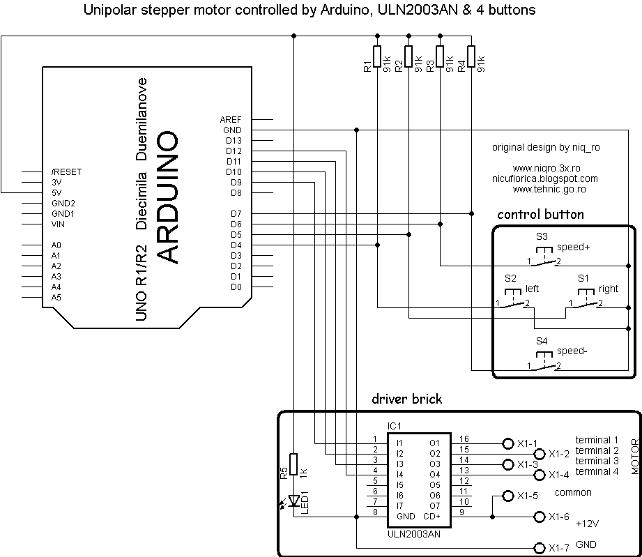
   Schema de conectare este:

   Am incercat sketch-ul din articolul Identifying and using a stepper motor on Arduino, modificand partea cu conectarea firelor:


/* Stepper Copal
 * -------------
 *
 * Program to drive a stepper motor coming from a 5'25 disk drive
 * according to the documentation I found, this stepper: "[...] motor 
 * made by Copal Electronics, with 1.8 degrees per step and 96 ohms 
 * per winding, with center taps brought out to separate leads [...]"
 * [http://www.cs.uiowa.edu/~jones/step/example.html]
 *
 * It is a unipolar stepper motor with 5 wires:
 * 
 * - red: power connector, I have it at 5V and works fine
 * - orange and black: coil 1
 * - brown and yellow: coil 2
 *
 * (cleft) 2005 DojoDave for K3
 * http://www.0j0.org | http://arduino.berlios.de
 *
 * @author: David Cuartielles
 * @date: 20 Oct. 2005
 */

int motorPin1 = 9;
int motorPin2 = 11;
int motorPin3 = 10;
int motorPin4 = 12;
int delayTime = 500;

void setup() {
  pinMode(motorPin1, OUTPUT);
  pinMode(motorPin2, OUTPUT);
  pinMode(motorPin3, OUTPUT);
  pinMode(motorPin4, OUTPUT);
}

void loop() {
  digitalWrite(motorPin1, HIGH);
  digitalWrite(motorPin2, LOW);
  digitalWrite(motorPin3, LOW);
  digitalWrite(motorPin4, LOW);
  delay(delayTime);
  digitalWrite(motorPin1, LOW);
  digitalWrite(motorPin2, HIGH);
  digitalWrite(motorPin3, LOW);
  digitalWrite(motorPin4, LOW);
  delay(delayTime);
  digitalWrite(motorPin1, LOW);
  digitalWrite(motorPin2, LOW);
  digitalWrite(motorPin3, HIGH);
  digitalWrite(motorPin4, LOW);
  delay(delayTime);
  digitalWrite(motorPin1, LOW);
  digitalWrite(motorPin2, LOW);
  digitalWrite(motorPin3, LOW);
  digitalWrite(motorPin4, HIGH);
  delay(delayTime);
}


   Filmuletul care prezinta modul de functionare se numeste first test with a unipolar stepper motor and Arduino:

   Apoi am testat sketch-ul din programul Arduino IDE numit "Steper_oneRevolution", modificand ordinea a 2 fire in program, apoi schimbandu-le fizic, deoarece in loc de rotire avea o miscare sacadata (fata-spate), filmuletul cu modul de functionare se numeste oneRevolution for a unipolar stepper motor and Arduino:

   La motorul testat am conectat culorile astfel:
- la D9 firul maro
- la D10 firul rosu
- la D11 firul galben
- la D12 firul albastru
- la +12V firul negru

/* 
 Stepper Motor Control - one revolution

 This program drives a unipolar or bipolar stepper motor. 
 The motor is attached to digital pins 9 - 12 of the Arduino.

 The motor should revolve one revolution in one direction, then
 one revolution in the other direction.  

 Created 11 Mar. 2007
 Modified 30 Nov. 2009
 by Tom Igoe

 */

#include <Stepper.h>

const int stepsPerRevolution = 100;  // change this to fit the number of steps per revolution
                                     // for your motor (se 

// initialize the stepper library on pins 9 through 12:
Stepper myStepper(stepsPerRevolution, 9,10,11,12);            

void setup() {
  // set the speed at xxx rpm:
  myStepper.setSpeed(100);
  // initialize the serial port:
  Serial.begin(9600);
}

void loop() {
  // step one revolution  in one direction:
   Serial.println("clockwise");
  myStepper.step(stepsPerRevolution);
  delay(500);
  
   // step one revolution in the other direction:
  Serial.println("counterclockwise");
  myStepper.step(-stepsPerRevolution);
  delay(500); 
}

   Pentru a scadea sau creste viteza de rotatie, se modifica:
 // set the speed at xxx rpm:
  myStepper.setSpeed(100);

   Am modificat acest sketch pentru a comanda rotirea mtorului intr-un sens sau altul prin apasarea a 2 butoane fara retinere (taste):

/* 
 use base of "Stepper Motor Control - one revolution" sketch made by Tom Igoe
 This program drives a unipolar stepper motor  with 2 button (clockwise or counterclockwise)
 The motor is attached to digital pins 9 - 12 of the Arduino.
 adapted sketch made by Nicu Florica (niq_ro) from http://tehnic.go.ro
 version 1.0 (07.04.2013 - Craiova, Romania)
 */

#include <Stepper.h>

const int stepsPerRevolution = 100;  // change this to fit the number of steps per revolution for your motor
Stepper myStepper(stepsPerRevolution, 9,10,11,12);     // initialize the stepper library on pins 9 through 12:
int speed = 50; // set the speed at 50 rpm:
int buton1 = 4;                 // first button at pin 4
int buton2 = 5;                 // second button at pin 5

void setup() {

  myStepper.setSpeed(speed); // set the speed
  Serial.begin(9600);   // initialize the serial port:
pinMode(buton1, INPUT);  // set buton1 pin as input
pinMode(buton2, INPUT);  // set buton2 pin as input
}

void loop() 
{
 digitalWrite(buton1, HIGH);  // if not pushed, set voltage for buton1 as HIGH 
 digitalWrite(buton2, HIGH);  // if not pushed, set voltage for buton1 as HIGH 

  if (digitalRead(buton1) == LOW) 
{
   Serial.println("clockwise");
  myStepper.step(stepsPerRevolution);
 }          

if (digitalRead(buton2) == LOW) 
{
   Serial.println("counterclockwise");
  myStepper.step(-stepsPerRevolution);
 }          

  delay(10); // waiting little bit...  

 // delay(10); // waiting little bit...  
}


   Am definit inca 2 taste, una pentru crestere viteza si una pentru reducere viteza, sketch-ul devenind versiunea 1m1:


/* 
 use base of "Stepper Motor Control - one revolution" sketch made by Tom Igoe
 This program drives a unipolar stepper motor  with 2 button (clockwise or counterclockwise) and 2 for speed
 The motor is attached to digital pins 9 - 12 of the Arduino.
 adapted sketch made by Nicu Florica (niq_ro) from http://tehnic.go.ro
http://nicuflorica.blogspot.com & http://www.niqro.3x.ro
 version 1m1 (07.04.2013 - Craiova, Romania)
 */

#include <Stepper.h>

const int stepsPerRevolution = 100;  // change this to fit the number of steps per revolution for your motor
Stepper myStepper(stepsPerRevolution, 9,10,11,12);     // initialize the stepper library on pins 9 through 12:
int viteza = 50; // set the speed at 50 rpm:
int buton1 = 4;                 // first button at pin 4
int buton2 = 5;                 // second button at pin 5
int buton3 = 6;                 // third button at pin 6
int buton4 = 7;                 // fourth button at pin 7


void setup() {

  myStepper.setSpeed(viteza); // set the speed
  Serial.begin(9600);   // initialize the serial port:
pinMode(buton1, INPUT);  // set buton1 pin as input
pinMode(buton2, INPUT);  // set buton2 pin as input
pinMode(buton3, INPUT);  // set buton3 pin as input
pinMode(buton4, INPUT);  // set buton4 pin as input

}

void loop() 
{
 digitalWrite(buton1, HIGH);  // if not pushed, set voltage for buton1 as HIGH 
 digitalWrite(buton2, HIGH);  // if not pushed, set voltage for buton1 as HIGH 
 digitalWrite(buton3, HIGH);  // if not pushed, set voltage for buton1 as HIGH 
 digitalWrite(buton4, HIGH);  // if not pushed, set voltage for buton1 as HIGH 

if (digitalRead(buton1) == LOW) 
{
   Serial.println("clockwise");
  myStepper.step(stepsPerRevolution);
 }          

if (digitalRead(buton2) == LOW) 
{
   Serial.println("counterclockwise");
  myStepper.step(-stepsPerRevolution);
 }          

  if (digitalRead(buton3) == LOW) 
{
   Serial.println("speed +");
   viteza = viteza*1.2;
   delay(250); // waiting little bit...  
 }          

  if (digitalRead(buton4) == LOW) 
{
   Serial.println("speed -");
   viteza = viteza*0.8;
   delay(250); // waiting little bit...  
 }          

  myStepper.setSpeed(viteza); // set the speed
  delay(10); // waiting little bit...  
 }


   Filmuletul care prezinta modul de comanda al motorului pas cu pas unipolar cu 4 taste (una pentru rotire in stanga, una pentru rotire in drepata, una pentru creste viteza si una pentru scadere viteza) se numeste control a unipolar stepper motor with 4 button and Arduino: