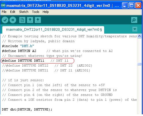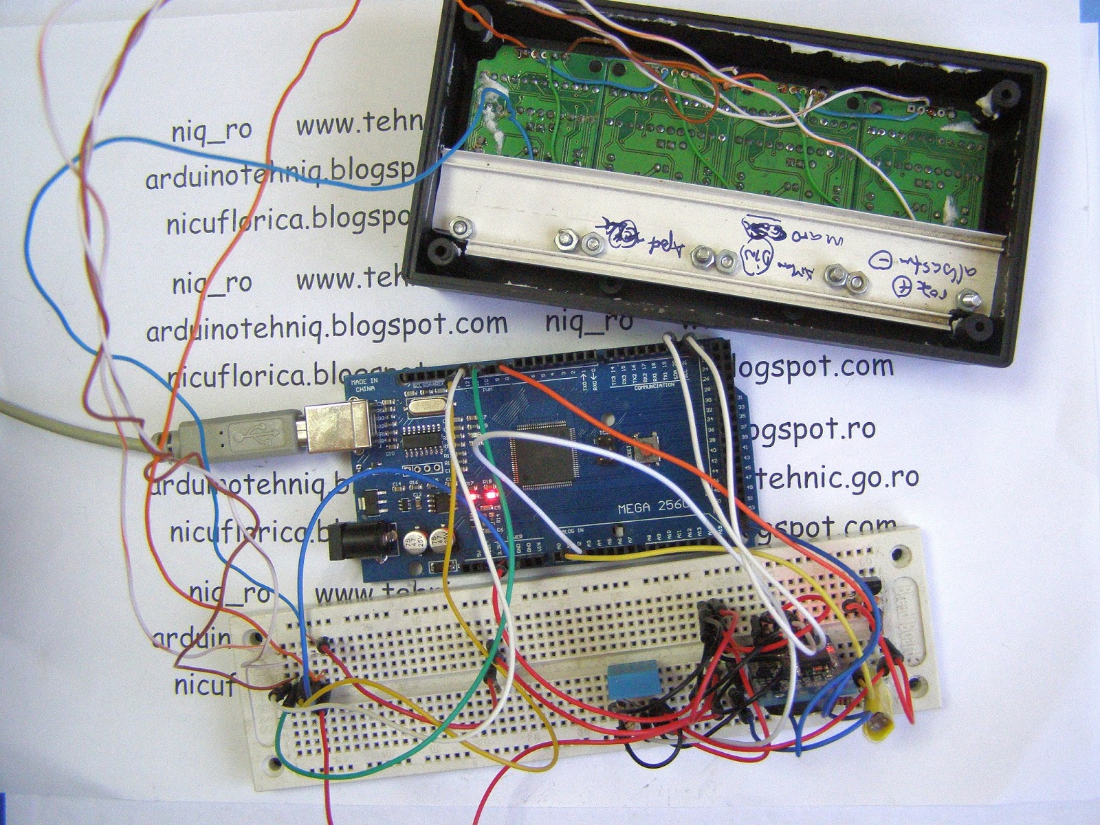
- ora:


Am facut si 2 filmulete:
- statie meteo si ceas cu data pe afisaj led de 32x8 leduri (5)


/**
 * I2C_ClearBus
 * (http://www.forward.com.au/pfod/ArduinoProgramming/I2C_ClearBus/index.html)
 * (c)2014 Forward Computing and Control Pty. Ltd.
 * NSW Australia, www.forward.com.au
 * This code may be freely used for both private and commerical use
 */

#include <Wire.h>

/**
 * This routine turns off the I2C bus and clears it
 * on return SCA and SCL pins are tri-state inputs.
 * You need to call Wire.begin() after this to re-enable I2C
 * This routine does NOT use the Wire library at all.
 *
 * returns 0 if bus cleared
 *         1 if SCL held low.
 *         2 if SDA held low by slave clock stretch for > 2sec
 *         3 if SDA held low after 20 clocks.
 */
int I2C_ClearBus() {
  TWCR &= ~(_BV(TWEN)); //Disable the Atmel 2-Wire interface so we can control the SDA and SCL pins directly

  pinMode(SDA, INPUT_PULLUP); // Make SDA (data) and SCL (clock) pins Inputs with pullup.
  pinMode(SCL, INPUT_PULLUP);

  delay(2500);  // Wait 2.5 secs. This is strictly only necessary on the first power
  // up of the DS3231 module to allow it to initialize properly,
  // but is also assists in reliable programming of FioV3 boards as it gives the
  // IDE a chance to start uploaded the program
  // before existing sketch confuses the IDE by sending Serial data.

  boolean SCL_LOW = (digitalRead(SCL) == LOW); // Check is SCL is Low.
  if (SCL_LOW) { //If it is held low Arduno cannot become the I2C master.
    return 1; //I2C bus error. Could not clear SCL clock line held low
  }

  boolean SDA_LOW = (digitalRead(SDA) == LOW);  // vi. Check SDA input.
  int clockCount = 20; // > 2x9 clock

  while (SDA_LOW && (clockCount > 0)) { //  vii. If SDA is Low,
    clockCount--;
  // Note: I2C bus is open collector so do NOT drive SCL or SDA high.
    pinMode(SCL, INPUT); // release SCL pullup so that when made output it will be LOW
    pinMode(SCL, OUTPUT); // then clock SCL Low
    delayMicroseconds(10); //  for >5uS
    pinMode(SCL, INPUT); // release SCL LOW
    pinMode(SCL, INPUT_PULLUP); // turn on pullup resistors again
    // do not force high as slave may be holding it low for clock stretching.
    delayMicroseconds(10); //  for >5uS
    // The >5uS is so that even the slowest I2C devices are handled.
    SCL_LOW = (digitalRead(SCL) == LOW); // Check if SCL is Low.
    int counter = 20;
    while (SCL_LOW && (counter > 0)) {  //  loop waiting for SCL to become High only wait 2sec.
      counter--;
      delay(100);
      SCL_LOW = (digitalRead(SCL) == LOW);
    }
    if (SCL_LOW) { // still low after 2 sec error
      return 2; // I2C bus error. Could not clear. SCL clock line held low by slave clock stretch for >2sec
    }
    SDA_LOW = (digitalRead(SDA) == LOW); //   and check SDA input again and loop
  }
  if (SDA_LOW) { // still low
    return 3; // I2C bus error. Could not clear. SDA data line held low
  }

  // else pull SDA line low for Start or Repeated Start
  pinMode(SDA, INPUT); // remove pullup.
  pinMode(SDA, OUTPUT);  // and then make it LOW i.e. send an I2C Start or Repeated start control.
  // When there is only one I2C master a Start or Repeat Start has the same function as a Stop and clears the bus.
  /// A Repeat Start is a Start occurring after a Start with no intervening Stop.
  delayMicroseconds(10); // wait >5uS
  pinMode(SDA, INPUT); // remove output low
  pinMode(SDA, INPUT_PULLUP); // and make SDA high i.e. send I2C STOP control.
  delayMicroseconds(10); // x. wait >5uS
  pinMode(SDA, INPUT); // and reset pins as tri-state inputs which is the default state on reset
  pinMode(SCL, INPUT);
  return 0; // all ok
}


void setup() {
  // put your setup code here, to run once:
  Serial.begin(9600);

  int rtn = I2C_ClearBus(); // clear the I2C bus first before calling Wire.begin()
  if (rtn != 0) {
    Serial.println(F("I2C bus error. Could not clear"));
    if (rtn == 1) {
      Serial.println(F("SCL clock line held low"));
    } else if (rtn == 2) {
      Serial.println(F("SCL clock line held low by slave clock stretch"));
    } else if (rtn == 3) {
      Serial.println(F("SDA data line held low"));
    }
  } else { // bus clear
    // re-enable Wire
    // now can start Wire Arduino master
    Wire.begin();
  }
  Serial.println("setup finished");
}

void loop() {
  // put your main code here, to run repeatedly:
  // do Wire RTC stuff here.
}