Schema folosita pentru teste este:
Zona colorata cu galben e partea de stabilizare de 5v realizata cu LM7805, pentru a putea alimenta montajul de la un alimentator sau masina... daca se fac teste cu alimentator de 5V, acea parte poate lipsi.
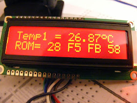
Pe ecran, cu 2 senzori DS18B20, am urmatoarele informatii:
In filmuletul ATTiny85 si DS18B20 se vede si faptul ca ATtiny85 sesiszeaza si cati senzori de temperatura de tip DS18B20 sunt conectati la el. Senzorii DS18B20 se pun in paralel, cum am prezentat in articolul Mai multi senzori de tip DS18B20 (sau MAX31820) in paralel (2).
Sketch-ul folosit de mine este:
/*
this sketch is adapted by niq_ro from
http://www.tehnic.go.ro
http://www.niqro.3x.ro
http://nicuflorica.blogspot.ro/
http://arduinotehniq.blogspot.com/
this sketch is made for use DS18B20 sensor(s) with ATtiny85 at 8MHz

 * 3-pin Arduino interface for HD44780 LCDs via 74HC595 Shift Register
 *     by Rowan Simms   code@rowansimms.com
 *     License: Creative Commons - Attribution.
 *     Full Documentation and Description:  http://rowansimms.com/article.php/lcd-hookup-in-seconds
 *
 * This sketch allows Arduinos to use a shift register to control an LCD, allowing
 * a reduction in pins it requires from 6 to 3 while still retaining full control
 * including backlight on/off.
 * This requires the use of the LiquidCrystal595 library
 * available at: http://code.google.com/p/arduino-lcd-3pin/
 */

#include <LiquidCrystal595.h>    // include the library
LiquidCrystal595 lcd(0,1,2);     // datapin, latchpin, clockpin

#include <OneWire.h>
// http://www.pjrc.com/teensy/td_libs_OneWire.html
// http://milesburton.com/Dallas_Temperature_Control_Library
OneWire  ds(3);  // on phiscal pin 2  (a 4.7K resistor is necessary)

byte grad[8] = {
  B01110,
  B10001,
  B10001,
  B01110,
  B00000,
  B00000,
  B00000,
};

int ics =0; //count number of sensor

void setup() {
    lcd.begin(16,2);             // 16 characters, 2 rows
 lcd.createChar(0, grad);

    lcd.clear();
    lcd.setCursor(0,0);
    lcd.print("Wow. 3 pins!");
    lcd.setCursor(0,1);
    lcd.print("Fabulous");
delay(2000);
lcd.clear();

  // Print a message to the LCD.
  lcd.setCursor(1, 0);
  lcd.print("temperatura in");
  lcd.setCursor(1, 1);
  lcd.print("mai multe zone");
  delay (2500);
  lcd.clear();
}


void loop() {
  byte i;
  byte present = 0;
  byte type_s;
  byte data[12];
  byte addr[8];
  float celsius;


  if ( !ds.search(addr)) {
    lcd.clear();
    lcd.setCursor(0, 1);
    lcd.print("doar ");
    lcd.print(ics);
    lcd.print(" senzor(i)");
    ds.reset_search();
    delay(250);
   ics=0;
    return;
  }

ics++;

  ds.reset();
  ds.select(addr);
  ds.write(0x44, 1);        // start conversion, with parasite power on at the end

  delay(1000);     // maybe 750ms is enough, maybe not
  // we might do a ds.depower() here, but the reset will take care of it.

  present = ds.reset();
  ds.select(addr);
  ds.write(0xBE);         // Read Scratchpad

  for ( i = 0; i < 9; i++) {           // we need 9 bytes
    data[i] = ds.read();
  }
  // Convert the data to actual temperature
  // because the result is a 16 bit signed integer, it should
  // be stored to an "int16_t" type, which is always 16 bits
  // even when compiled on a 32 bit processor.
  int16_t raw = (data[1] << 8) | data[0];
  if (type_s) {
    raw = raw << 3; // 9 bit resolution default
    if (data[7] == 0x10) {
      // "count remain" gives full 12 bit resolution
      raw = (raw & 0xFFF0) + 12 - data[6];
    }
  } else {
    byte cfg = (data[4] & 0x60);
    // at lower res, the low bits are undefined, so let's zero them
    if (cfg == 0x00) raw = raw & ~7;  // 9 bit resolution, 93.75 ms
    else if (cfg == 0x20) raw = raw & ~3; // 10 bit res, 187.5 ms
    else if (cfg == 0x40) raw = raw & ~1; // 11 bit res, 375 ms
    //// default is 12 bit resolution, 750 ms conversion time
  }

lcd.clear();
lcd.setCursor(0, 1);
  lcd.print("ROM=");
  for( i = 0; i < 8; i++) {
    lcd.print(' ');
    lcd.print(addr[i], HEX);
  }

  if (OneWire::crc8(addr, 7) != addr[7]) {
      lcd.print("CRC is not valid!");
      return;
  }

  celsius = (float)raw / 16.0;

  lcd.setCursor(0,0);
  lcd.print("Temp");
  lcd.print(ics);
  lcd.print(" = ");
  lcd.print(celsius);
  lcd.write(byte(0));
  lcd.print("C   ");

  delay(3000);
}


Niciun comentariu:
Trimiteți un comentariu